CDL.Continuous.Validation
Collection of models that validate the continuous blocks of the CDL
Information
This package contains models that validate the blocks in CDL.Continuous.
The examples plot various outputs, which have been verified against analytical solutions. These model outputs are stored as reference data to allow continuous validation whenever models in the library change.
Package Content
| Name | Description |
|---|---|
| Validation model for the absolute block | |
| Validation model for the Acos block | |
| Validation model for the add block | |
| Validation model for the AddParameter block | |
| Validation model for the Asin block | |
| Validation model for the Atan block | |
| Validation model for the Atan2 block | |
| Validation model for the Average block | |
| Validation model for the Cos block | |
| Test model for the derivative block | |
| Validation model for the Divide block | |
| Validation model for the Exp block | |
| Validation model for the Greater block | |
| Validation model for the GreaterThreshold block | |
| Validation model for the Hysteresis block | |
| Test model for integrator with reset | |
| Validation model for the Less block | |
| Validation model for the LessThreshold block | |
| Validation model for the LimitSlewRate block | |
| Validation model for the Limiter block | |
| Validation model for the Line block | |
| Validation model for the Log block | |
| Validation model for the Log10 block | |
| Validation model for the MatrixGain block | |
| Validation model for the MatrixMax block | |
| Validation model for the MatrixMin block | |
| Validation model for the Max block | |
| Validation model for the Min block | |
| Validation model for the Modulo block | |
| Validation model for the MovingAverage block | |
| Validation model for the MovingAverage block | |
| Validation model for the MultiMax block | |
| Validation model for the MultiMin block | |
| Model to validate the application of MultiSum block | |
| Validation model for the Multiply block | |
| Validation model for the Gain block | |
| Test model for PID controller | |
| Test model for LimPID controller with initial output of the derivative term specified | |
| Test model for LimPID controller with initial state specified | |
| Test model for PID controller with scaling of the control error | |
| Test model for LimPID controller with reset trigger | |
| Test model for PID controller with reset and scaling of the control error | |
| Validation model for the Ramp block | |
| Validation model for the Round block | |
| Validation model for the Sin block | |
| Validation model for the Sort block | |
| Validation model for the Sqrt block | |
| Validation model for the Subtract block | |
| Validation model for the Switch block | |
| Validation model for the Tan block |
 CDL.Continuous.Validation.Abs
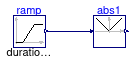
Validation model for the absolute block
Information
Validation test for the block CDL.Continuous.Abs. The input varies from -1 to +1.
Modelica definition
CDL.Continuous.Validation.Acos
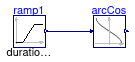
Validation model for the Acos block
Information
Validation test for the block CDL.Continuous.Acos.
The input u varies from -1 to +1.
Modelica definition
CDL.Continuous.Validation.Add
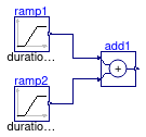
Validation model for the add block
Information
Validation test for the block CDL.Continuous.Add.
The input u1 varies from -2 to +2, input u2 varies from -1 to +1.
Modelica definition
CDL.Continuous.Validation.AddParameter
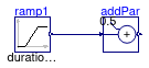
Validation model for the AddParameter block
Information
Validation test for the block CDL.Continuous.AddParameter.
The input u varies from -2 to +2.
Modelica definition
CDL.Continuous.Validation.Asin
Validation model for the Asin block
Information
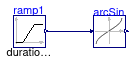
Validation test for the block CDL.Continuous.Asin.
The input u varies from -1 to +1.
Modelica definition
CDL.Continuous.Validation.Atan
Validation model for the Atan block
Information
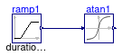
Validation test for the block CDL.Continuous.Atan.
The input u varies from -2 to +2.
Modelica definition
CDL.Continuous.Validation.Atan2
Validation model for the Atan2 block
Information
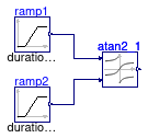
Validation test for the block CDL.Continuous.Atan2.
The input u1 varies from -2 to +2,
The input u2 varies from +1 to +3.
Modelica definition
CDL.Continuous.Validation.Average
Validation model for the Average block

Information
Validation test for the block CDL.Continuous.Average.
The input u1 varies from -2.0 to +6.0, input u2 varies from +1.5 to +4.5
Modelica definition
CDL.Continuous.Validation.Cos
Validation model for the Cos block
Information
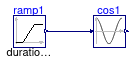
Validation test for the block CDL.Continuous.Cos.
The input u varies from 0.0 to +6.283.
Modelica definition
CDL.Continuous.Validation.Derivative
Test model for the derivative block
Information
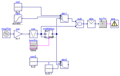
Validation test for the block
CDL.Continuous.Derivative.
The model integrates a time varying signal, and the differentiates this integrated signal.
Hence, the output der1.y matches the non-integrated signal intWitRes.u,
within a small approximation tolerance.
The instance der1 uses a varying input for T which controls the accuracy of
the derivative approximation. At the start of the simulation, T is small and hence
the output der1.y matches the signal intWitRes.u well.
As expected, the approximation error increases with increasing der1.T.
The instance der2 uses a gain of 2, and it initializes the output to 0.
Hence, there is a fast transient at the beginning, and afterwards the output matches der1.y = der2.y / 2.
Modelica definition
CDL.Continuous.Validation.Divide
Validation model for the Divide block
Information
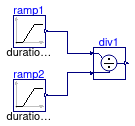
Validation test for the block CDL.Continuous.Divide.
The input u1 varies from -2 to +2, input u2 varies from +1 to +3.
Modelica definition
CDL.Continuous.Validation.Exp
Validation model for the Exp block
Information
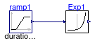
Validation test for the block CDL.Continuous.Exp.
The input u varies from 0.0 to +2.
Modelica definition
CDL.Continuous.Validation.Greater
Validation model for the Greater block
Information
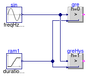
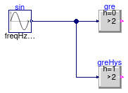
Validation test for the block
CDL.Continuous.Greater.
The instance gre has no hysteresis, and the
instance greHys has a hysteresis.
Modelica definition
CDL.Continuous.Validation.GreaterThreshold
Validation model for the GreaterThreshold block
Information
Validation test for the block
CDL.Continuous.GreaterThreshold.
The instance gre has no hysteresis, and the
instance greHys has a hysteresis.
Modelica definition
CDL.Continuous.Validation.Hysteresis
Validation model for the Hysteresis block
Information
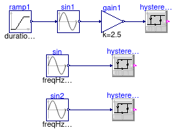
Validation test for the block CDL.Continuous.Hysteresis.
Modelica definition
CDL.Continuous.Validation.IntegratorWithReset
Test model for integrator with reset
Information
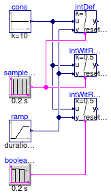
This model tests the implementation of CDL.Continuous.IntegratorWithReset with and without reset, and with different start values and reset values.
The integrator intWitRes1 is triggered by a sample trigger
which becomes true at t=0, while intWitRes2 is triggered
by a boolean pulse with is true at t=0.
Hence, intWitRes1 starts with y(0)=y_reset while
intWitRes2 starts with y(0)=y_start.
Modelica definition
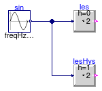
CDL.Continuous.Validation.Less
Validation model for the Less block
Information
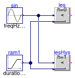
Validation test for the block
CDL.Continuous.Less.
The instance les has no hysteresis, and the
instance lesHys has a hysteresis.
Modelica definition
CDL.Continuous.Validation.LessThreshold
Validation model for the LessThreshold block
Information
Validation test for the block
CDL.Continuous.LessThreshold.
The instance les has no hysteresis, and the
instance lesHys has a hysteresis.
Modelica definition
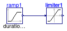
CDL.Continuous.Validation.LimitSlewRate
Validation model for the LimitSlewRate block
Information
Validation test for the block CDL.Continuous.LimitSlewRate.
The input ramp1.u varies from 0 to +1.5,
in 1 s.
The increase and decrease rate limits are [increase/incDt, -decrease/decDt] , which is [1, -1] here.
Modelica definition
CDL.Continuous.Validation.Limiter
Validation model for the Limiter block
Information
Validation test for the block CDL.Continuous.Limiter.
The input u varies from 0.0 to +2.
Modelica definition
CDL.Continuous.Validation.Line
Validation model for the Line block
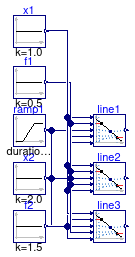
Information
Validation test for the block CDL.Continuous.Line.
The input u varies from 0.0 to +2.
The block outputs y = a + b u,
where
u is an input
and the coefficients a and b
are determined so that the line intercepts the two input points
specified by the two points x1 and f1,
and x2 and f2.
The parameters limitBelow and limitAbove
determine whether x1 and x2 are also used
to limit the input u.
Modelica definition
CDL.Continuous.Validation.Log
Validation model for the Log block
Information
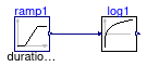
Validation test for the block CDL.Continuous.Log.
The input u varies from +1 to +6.
Modelica definition
CDL.Continuous.Validation.Log10
Validation model for the Log10 block
Information
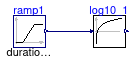
Validation test for the block CDL.Continuous.Log10.
The input u varies from +1 to +10.
Modelica definition
CDL.Continuous.Validation.MatrixGain
Validation model for the MatrixGain block
Information
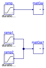
Validation test for the block CDL.Continuous.MatrixGain.
The input vector output two identical values u[1] and
u[2] that vary from 0.0 to +2.
Modelica definition
CDL.Continuous.Validation.MatrixMax
Validation model for the MatrixMax block
Information
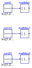
Validation test for the block CDL.Continuous.MatrixMax.
Modelica definition
CDL.Continuous.Validation.MatrixMin
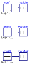
Validation model for the MatrixMin block
Information
Validation test for the block CDL.Continuous.MatrixMin.
Modelica definition
CDL.Continuous.Validation.Max
Validation model for the Max block
Information
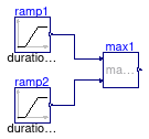
Validation test for the block CDL.Continuous.Max.
The input u1 varies from -2 to +2, input u2 varies from -1 to +1.
Modelica definition
CDL.Continuous.Validation.Min
Validation model for the Min block

Information
Validation test for the block CDL.Continuous.Min.
The input u1 varies from -2 to +2, input u2 varies from -1 to +1.
Modelica definition
CDL.Continuous.Validation.Modulo
Validation model for the Modulo block
Information
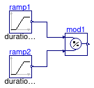
Validation test for the block CDL.Continuous.Modulo.
The input u1 varies from -2.0 to +6.0, input u2 varies from +1.5 to +4.5
Modelica definition
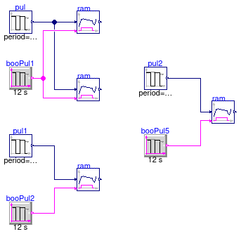
CDL.Continuous.Validation.MovingAverage
Validation model for the MovingAverage block
Information
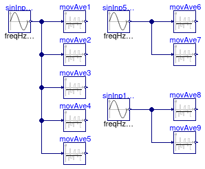
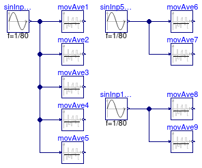
Validation test for the block CDL.Continuous.MovingAverage.
The input sinInpNoDel, sinInp50sDel,
sinInp100sDel, generate sine outputs with same frequency of
1/80 Hz, but different start times of 0 second,
50 second, 100 second.
Modelica definition
CDL.Continuous.Validation.MovingAverage_nonZeroStart
Validation model for the MovingAverage block
Information
Validation test for the block CDL.Continuous.MovingAverage.
The inputs sinInpNoDel, sinInp50sDel and
sinInp100sDel generate sine outputs with the same frequency of
1/80 Hertz, but different start times of 0 seconds,
50 seconds and 100 seconds.
Modelica definition
CDL.Continuous.Validation.MultiMax
Validation model for the MultiMax block
Information
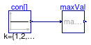
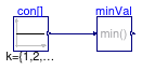
Validation test for the block CDL.Continuous.MultiMax.
The input vectorcon has size 5 and its element values are {1,2,3,4,5}.
Parameters
| Type | Name | Default | Description |
|---|---|---|---|
| Integer | sizOfVec | 5 | Size of the input vector |
Modelica definition
CDL.Continuous.Validation.MultiMin
Validation model for the MultiMin block
Information
Validation test for the block CDL.Continuous.MultiMin.
The input vectorcon has size 5 and its element values are {1,2,3,4,5}.
Parameters
| Type | Name | Default | Description |
|---|---|---|---|
| Integer | sizOfVec | 5 | Size of the input vector |
Modelica definition
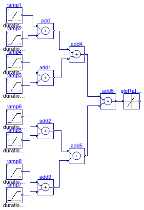
CDL.Continuous.Validation.MultiSum
Model to validate the application of MultiSum block
Information
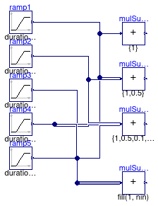
Validation test for the block CDL.Continuous.MultiSum.
The inputs and gains are configured as follows:
- u1 varies from -2 to +2, with gain k = 1.
- u2 varies from -1 to +1, with gain k = 0.5.
- u3 varies from -1 to +2, with gain k = 0.1.
- u4 varies from -2 to +1, with gain k = 1.
- u5 varies from -3 to 0, with gain k = 2.
Modelica definition
CDL.Continuous.Validation.Multiply
Validation model for the Multiply block
Information
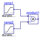
Validation test for the block CDL.Continuous.Multiply.
The input u1 varies from -2 to +2, input u2 varies from -1 to +2.
Modelica definition
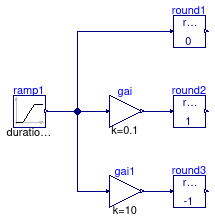
CDL.Continuous.Validation.MultiplyByParameter
Validation model for the Gain block
Information
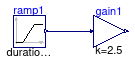
Validation test for the block CDL.Continuous.MultiplyByParameter.
The input u varies from 0.0 to +2.
Modelica definition
CDL.Continuous.Validation.PID
Test model for PID controller
Information
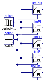
Validation test for the block CDL.Continuous.PID. This tests the different settings for the controller types.
Modelica definition
CDL.Continuous.Validation.PIDInitialDerivativeOutput
Test model for LimPID controller with initial output of the derivative term specified
Information
Validation test for the block CDL.Continuous.PID.
This model validates setting the initial output of the controller to a specified value. Note that the control error must be zero for the initial output to be at the specified value. See the description of CDL.Continuous.PID.
Modelica definition
CDL.Continuous.Validation.PIDInitialState
Test model for LimPID controller with initial state specified
Information
Validation test for the block CDL.Continuous.PID.
This model validates setting the initial state of the controller to a specified value.
The model sets the initial values xi_start=0.25
of the integrator for both instances of the controller.
For the instance limPID, it also sets the initial value of the state of the
derivative block xd_start=-0.5.
The derivative block obtains as an input signal the value
u=-0.5 because the set point weight for the derivative action is wd=0.
Therefore, an initial state of x(t0)=-0.5 causes the state of the derivative
block to be at steady-state, because
dx(t)/dt = (u - x)/T.
Modelica definition
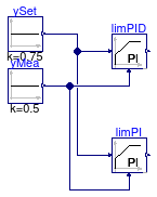
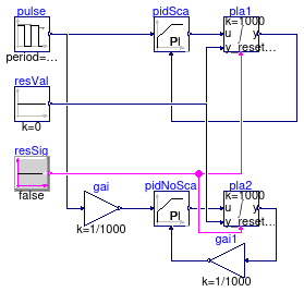
CDL.Continuous.Validation.PIDScale
Test model for PID controller with scaling of the control error
Information
Validation test for the block CDL.Continuous.PID with and without setting of the parameter that scales the control error.
The test has two combinations of a PID controller and a plant.
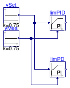
In PIDSca, the control error is scaled inside the controller, whereas
in the configuration that has PIDNoSca, the setpoint signal and the
measurement signal is scaled outside of the controller.
Both controllers and plants have the same trajectory, thereby validating that
the scaling is implemented correctly.
Modelica definition
CDL.Continuous.Validation.PIDWithReset
Test model for LimPID controller with reset trigger
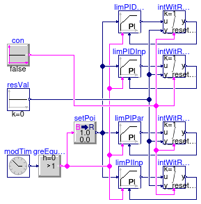
Information
Validation test for the block CDL.Continuous.PID.
This model validates the controller for different settings of the control output reset.
Modelica definition
CDL.Continuous.Validation.PIDWithResetScale
Test model for PID controller with reset and scaling of the control error
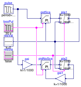
Information
Validation test for the block CDL.Continuous.PIDWithReset with and without setting of the parameter that scales the control error.
The test has two combinations of a PID controller and a plant.
In PIDSca, the control error is scaled inside the controller, whereas
in the configuration that has PIDNoSca, the setpoint signal and the
measurement signal is scaled outside of the controller.
Both controllers and plants have the same trajectory, thereby validating that
the scaling is implemented correctly.
Modelica definition
CDL.Continuous.Validation.Ramp
Validation model for the Ramp block
Information
Validation test for the block CDL.Continuous.Ramp.
-
The instances
ramUpandramUp1shows ramping up the input in different speed. -
The instance
ramUpDowshows ramping up and down the input in the same speed. It also shows that the output will be the ramped input if the boolean inputactiveistrue. -
The instance
ramUpDow1shows ramping up and down the input in the different speed.
Modelica definition
CDL.Continuous.Validation.Round
Validation model for the Round block
Information
Validation test for the block CDL.Continuous.Round.
The input u varies from -3.5 to +3.5.
Modelica definition
CDL.Continuous.Validation.Sin
Validation model for the Sin block
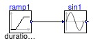
Information
Validation test for the block CDL.Continuous.Sin.
The input u varies from 0.0 to +2π.
Modelica definition
CDL.Continuous.Validation.Sort
Validation model for the Sort block
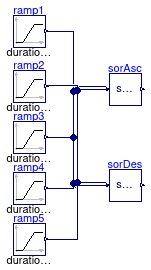
Information
Validation test for the block CDL.Continuous.Sort.
The input u1 varies from -2 to +2, input u2 varies from -1 to +2,
input u3 varies from +2 to -2, input u4 varies from +3 to +2,
input u5 varies from 0 to +4,
Modelica definition
CDL.Continuous.Validation.Sqrt
Validation model for the Sqrt block
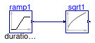
Information
Validation test for the block CDL.Continuous.Sqrt.
The input u varies from 0.0 to +9.0.
Modelica definition
CDL.Continuous.Validation.Subtract
Validation model for the Subtract block
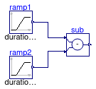
Information
Validation test for the block CDL.Continuous.Subtract.
The input u1 varies from -2 to +2, input u2 varies from -1 to +1.
Modelica definition
CDL.Continuous.Validation.Switch
Validation model for the Switch block
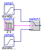
Information
Validation test for the block CDL.Continuous.Switch.
Modelica definition
CDL.Continuous.Validation.Tan
Validation model for the Tan block
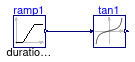
Information
Validation test for the block CDL.Continuous.Tan.
The input u varies from -1.5 to +1.5.