CDL.Logical.Validation
Collection of models that validate the logical blocks of the CDL
Information
This package contains models that validate the blocks in CDL.Logical.
The examples plot various outputs, which have been verified against analytical solutions. These model outputs are stored as reference data to allow continuous validation whenever models in the library change.
Package Content
| Name | Description |
|---|---|
| Validation model for the And block | |
| Validation model for the And3 block | |
| Validation model for the Change block. | |
| Validation model for the Edge block | |
| Validation model for the falling edge block | |
| Validation model for the Latch block | |
| Model to validate the application of MultiAnd block | |
| Model to validate the application of MultiOr block | |
| Validation model for the Nand block | |
| Validation model for the Nor block | |
| Validation model for the Not block | |
| Validation model for the OnOffController block | |
| Validation model for the Or block | |
| Validation model for the Or3 block | |
| Validation model for the Proof block | |
| Validation model for the Switch block | |
| Validation model for the Timer block | |
| Validation model for the timer that accumulates the time | |
| Validation model for the timer that accumulates the time, with a negative start time | |
| Validation model for the Timer block with a negative start time | |
| Validation model for the Toggle block | |
| Validation model for the TriggeredTrapezoid block | |
| Validation model for the TrueDelay block | |
| Validation model for the TrueFalseHold block | |
| Validation model for the TrueHoldWithReset block | |
| Validation model for producing boolean pulse output | |
| Validation model for producing boolean pulse output | |
| Validation model for the Xor block | |
| Validation model for the zero crossing block |
 CDL.Logical.Validation.And
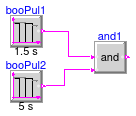
Validation model for the And block
Information
Validation test for the block CDL.Logical.And.
Modelica definition
CDL.Logical.Validation.And3
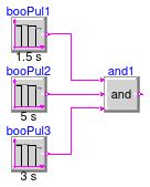
Validation model for the And3 block
Information
Validation test for the block CDL.Logical.And3.
Modelica definition
CDL.Logical.Validation.Change
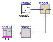
Validation model for the Change block.
Information
Validation test for the block CDL.Logical.Change.
Modelica definition
CDL.Logical.Validation.Edge
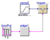
Validation model for the Edge block
Information
Validation test for the block CDL.Logical.Edge.
Modelica definition
CDL.Logical.Validation.FallingEdge
Validation model for the falling edge block
Information
Validation test for the block CDL.Logical.FallingEdge.
Modelica definition
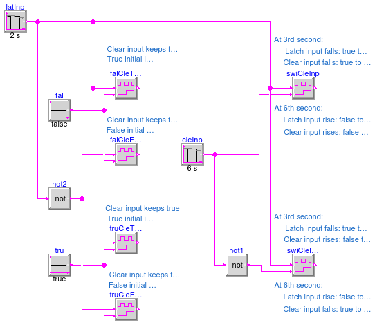
CDL.Logical.Validation.Latch
Validation model for the Latch block
Information
Validation test for the block CDL.Logical.Latch. Following tests are implemented:
-
When the clear input is
false, the initial output should equal to the initial latch input. -
When the clear input is
true, the initial output should befalse, regardless of the value of the latch input. -
At the same moment, when both the clear input and the latch input rise from
falsetotrue, the output should becomefalseif it wastrue, or remainfalseif it wasfalse. -
At the same moment, when the clear input falls from
truetofalseand the latch input rises fromfalsetotrue, the output should rise fromfalsetotrue.
Modelica definition
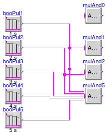
CDL.Logical.Validation.MultiAnd
Model to validate the application of MultiAnd block
Information
Validation test for the block CDL.Logical.MultiAnd.
The input signals are configured as follows:
- input u1 has a period of 1 s and a width of 0.5 s.
- input u2 has a period of 2 s and a width of 0.5 s.
- input u3 has a period of 3 s and a width of 0.5 s.
- input u4 has a period of 4 s and a width of 0.5 s.
- input u5 has a period of 5 s and a width of 0.5 s.
Modelica definition
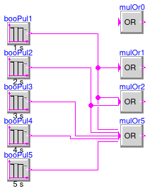
CDL.Logical.Validation.MultiOr
Model to validate the application of MultiOr block
Information
Validation test for the block CDL.Logical.MultiOr.
The input signals are configured as follows:
- input u1 has a period of 1 s and a width of 0.5 s.
- input u2 has a period of 2 s and a width of 0.5 s.
- input u3 has a period of 3 s and a width of 0.5 s.
- input u4 has a period of 4 s and a width of 0.5 s.
- input u5 has a period of 5 s and a width of 0.5 s.
Modelica definition
CDL.Logical.Validation.Nand
Validation model for the Nand block
Information
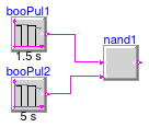
Validation test for the block CDL.Logical.Nand.
Modelica definition
CDL.Logical.Validation.Nor
Validation model for the Nor block
Information
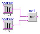
Validation test for the block CDL.Logical.Nor.
Modelica definition
CDL.Logical.Validation.Not
Validation model for the Not block
Information
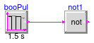
Validation test for the block CDL.Logical.Not.
Modelica definition
CDL.Logical.Validation.OnOffController
Validation model for the OnOffController block
Information
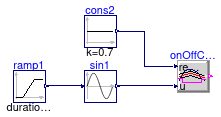
Validation test for the block CDL.Logical.OnOffController.
Modelica definition
CDL.Logical.Validation.Or
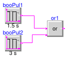
Validation model for the Or block
Information
Validation test for the block CDL.Logical.Or.
Modelica definition
CDL.Logical.Validation.Or3
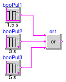
Validation model for the Or3 block
Information
Validation test for the block CDL.Logical.Or3.
Modelica definition
CDL.Logical.Validation.Proof
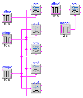
Validation model for the Proof block
Information
Validation test for the block CDL.Logical.Proof. The following tests are implemented:
-
The instance
protests the case in which both boolean inputs change simultaneously, and hence both outputs will befalse. -
The instances
pro2andpro3use a different value forfeedbackDelay. They test the case in which both the inputs change fromtruetofalse. However, after the inputu_mchanges, the inputu_sremainstruefor a time that is longer thanfeedbackDelay. The outputyLocFalwill betrue. -
The instances
pro1andpro4use a different value forfeedbackDelay. They test the case in which both the inputs change fromtruetofalse. However, after the inputu_schanges, the inputu_mremainstruefor a time that is longer thanfeedbackDelay. The outputyLocTruwill betrue. -
The instance
pro5tests the case in which the measured inputu_mdoes not stabilize during the debounce time, and hence both outputs will betrue.
Modelica definition
CDL.Logical.Validation.Switch
Validation model for the Switch block
Information
Validation test for the block CDL.Logical.Switch.
The input u2 is the switch input: If u2 = true,
then output y = u1;
else output y = u3.
Modelica definition
CDL.Logical.Validation.Timer
Validation model for the Timer block
Information
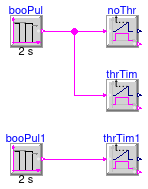
Validation test for the block CDL.Logical.Timer.
Modelica definition
CDL.Logical.Validation.TimerAccumulating
Validation model for the timer that accumulates the time
Information
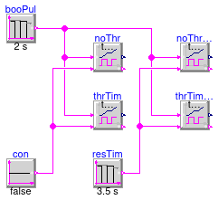
Validation test for the block CDL.Logical.TimerAccumulating.
Modelica definition
CDL.Logical.Validation.TimerAccumulatingNegativeStartTime
Validation model for the timer that accumulates the time, with a negative start time

Information
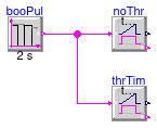
Validation test for the block CDL.Logical.TimerAccumulating.
Modelica definition
CDL.Logical.Validation.TimerNegativeStartTime
Validation model for the Timer block with a negative start time
Information
Validation test for the block CDL.Logical.Timer.
Modelica definition
CDL.Logical.Validation.Toggle
Validation model for the Toggle block
Information
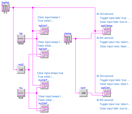
Validation test for the block CDL.Logical.Toggle. Following tests are implemented:
-
When the clear input is
false, the initial output should equal to the initial toggle input. -
When the clear input is
true, the initial output should befalse, regardless of the value of the toggle input. -
At the same moment, when both the clear input and the toggle input rise from
falsetotrue, the output should becomefalseif it wastrue, or remainfalseif it wasfalse. -
At the same moment, when the clear input falls from
truetofalseand the toggle input rises fromfalsetotrue, the output should rise fromfalsetotrue.
Modelica definition
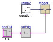
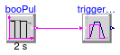
CDL.Logical.Validation.TriggeredTrapezoid
Validation model for the TriggeredTrapezoid block
Information
Validation test for the block CDL.Logical.TriggeredTrapezoid.
Modelica definition
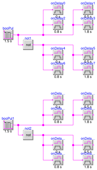
CDL.Logical.Validation.TrueDelay
Validation model for the TrueDelay block
Information
Validation test for the block CDL.Logical.TrueDelay.
Modelica definition
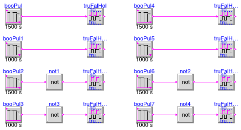
CDL.Logical.Validation.TrueFalseHold
Validation model for the TrueFalseHold block
Information
Validation test for the block CDL.Logical.TrueFalseHold.
The validation uses different instances to validate different hold trueHoldDurations, different lengths of the input pulse, and different initial values for the input signal.
Modelica definition
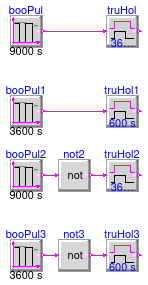
CDL.Logical.Validation.TrueHoldWithReset
Validation model for the TrueHoldWithReset block
Information
Validation test for the block CDL.Logical.TrueHoldWithReset.
The validation uses different instances to validate different hold durations, different lengths of the input pulse, and different initial values for the input signal.
Modelica definition
CDL.Logical.Validation.VariablePulse
Validation model for producing boolean pulse output
Information
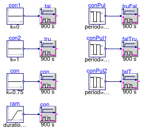
Validation test for the block CDL.Logical.VariablePulse.
-
The instance
falhas the constant0input. It gives constantfalseoutput. -
The instance
truhas the constant1input. It gives constanttrueoutput. -
The instance
conTruhas the constant0.75input. It gives the pulse output, with the width (75%). -
The instance
truFalhas the input changing from0.65to0. It outputs a pulse (with the width of 65%) and then changes to constantfalse. -
The instance
falTruhas the input changing from0to0.65and then back to0. It firstly outputs the constantfalse, then a pulse (with the width of 65%) and finally back tofalse. -
The instance
falTru1has the input changing from0.3to0.8and then back to0.3. It firstly outputs a pulse with the width of 30%, then a pulse with the width of 80%, and finally a pulse with the width of 30% again. When the input changes, it gives a new pulse immediately. -
The instance
conChaWidhas a ramp input. It gives constanttrueoutput when the input is ramping up.
Modelica definition
CDL.Logical.Validation.VariablePulseMinHold
Validation model for producing boolean pulse output
Information
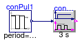
Validation test for the block CDL.Logical.VariablePulse.
It tests the case that the input value changes at the moment when the output is still in previous status in less than the minimum holding time. In the case, the output holds the previous status for the minimum holding time and then change to the new status.
Modelica definition
CDL.Logical.Validation.Xor
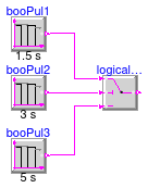
Validation model for the Xor block
Information
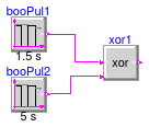
Validation test for the block CDL.Logical.Xor.
Modelica definition
CDL.Logical.Validation.ZeroCrossing
Validation model for the zero crossing block
Information
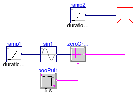
Validation test for the block CDL.Logical.ZeroCrossing.