7. Control Description Language
7.1. Introduction
This section specifies the Control Description Language (CDL), a declarative language that can be used to express control sequences using block-diagrams. CDL has been developed originally in the OpenBuildingControl project, and then underwent updates through the ASHRAE Standard 231 Committee and is now standardized as ANSI/ASHRAE Standard 231. This page gives an informal specification of CDL that is consistent with ANSI/ASHRAE Standard 231. A reference implementation of CDL as well as control sequences that were implemented using CDL are available from the Modelica Buildings Library. See https://obc.lbl.gov/overview.html for an overview.
CDL was designed in such a way that it can be used to conveniently specify building control sequences in a vendor-independent format, use them within whole building energy simulation, and translate them for use in building control systems. A key technical challenge encountered when developing CDL was that existing control product lines are heterogeneous. They differ in their functionality for expressing control sequences, in their semantics of how control output gets updated, and in their syntax which ranges from graphical languages to textual languages. Code generation for a variety of products is common in the Electronic Design Automation industry. However, in the Electronic Design Automation industry, engineers write models and controllers are built to conform to the models. If this were to be applied to the buildings industry, then control providers would need to update their product line in order to be able to faithfully comply with the model. We think such costly product line reconfigurations are not reasonable to expect in the next decade. Therefore, for the immediate future, we will need to build digital models of control sequences that can conform to their implementation on target control product lines; while ensuring that as new product lines are being developed, the manufacturers can invert the paradigm and build controllers that conform to the models. We therefore selected the path of designing CDL in such a way that it provide a minimum set of capabilities that can be expected to be supported by current control product lines, while allowing future control product lines to directly use CDL for the implementation of the control sequences. As we have demonstrated with one commercial product, the barrier to translate CDL to the programming language of a current control product line is low.
Fig. 7.1 Translation of CDL to the CDL-JSON intermediate format and to a product line, a semantic model or English language documentation.
To put CDL in context, and to introduce terminology, Fig. 7.1 shows the translation of CDL to a control product line
or to English language documentation.
Input into the translation is CDL. An open-source tool called modelica-json translator
(see also Section 11.3 and https://github.com/lbl-srg/modelica-json)
translates CDL to an intermediate format that we call CDL-JSON.
From CDL-JSON, further translations can be done to a control product line, or to
generate point lists, English language documentation or a semantic model of the control sequences.
We anticipate that future control product lines use directly CDL as shown in the right of
Fig. 7.1. Such a translation can then be done using
various existing Modelica tools to generate code for real-time simulation.
The next sections give an overview and definition of the CDL language.
A collection of control sequences that are composed using the CDL language is described
in Section 10. These sequences can be simulated with Modelica simulation environments.
The translation of such sequences to control product lines using modelica-json,
or other means of translation, is described in
Section 11.
7.2. Overview of CDL and Terminology
CDL is a declarative, modular language for expressing block diagrams that was introduced in [WGH18]. CDL allows hierarchical modeling to encapsulate and reuse, through object instantiation, preconfigured control sequences. CDL also defines syntax for connecting inputs and outputs of blocks and for propagating the values of parameters. CDL allows users to declare new blocks, store them in a library, and instantiate them for use in a control sequence. CDL also has annotations that declare how to graphically render the block diagrams, and to document control sequences.
CDL uses a small subset of the Modelica language that is needed for declaration of block diagrams. We selected Modelica as it is an open standard, as it provides various open-source and commercial modeling and simulation environments, as it allows to generate highly efficient code for simulation, and because it is increasingly used to simulate building energy and control systems.
As the model of computation, CDL uses the synchronous data flow principle and single assignment rule, which is consistent with the Modelica Language Specification [Mod23]. Therefore, all variables keep their value until the value is explicitly changed, values are always present (and hence can be accessed at any time instant), computation and communication at an event instant do not take time, and every input connector must be connected to exactly one output connector.
CDL consists of three types of blocks:
Elementary blocks: These are built-in blocks that cannot be changed by users. All implementations of CDL need to provide the functionality of these blocks. An example is a block that outputs the sum of two inputs.
Composite blocks: These are blocks that are composed hierarchically using elementary blocks or other composite blocks. Composite blocks can be used to declare control sequences, they can be stored in a library for reuse, and they can be instantiated and configured for a particular energy system.
Extension blocks: Extension blocks allow users to implement new blocks that may be difficult or impossible to implement using the rules of composite blocks. For example, an extension block could be used to call a web service, or to implement a finite state machine that rotates chillers in a chiller plant.
The functionality of elementary blocks, but not their implementation, is part of the CDL specification. Thus, in the most general form, elementary blocks can be considered as functions that for given parameters \(p\), time \(t\) and internal state \(x(t)\), map inputs \(u(t)\) to new values for the outputs \(y(t)\) and states \(x'(t)\), e.g., \((p, t, u(t), x(t)) \mapsto (y(t), x'(t))\). By the composition rules of composite blocks, composite blocks are also such functions. This abstraction is important as it allows to execute CDL sequences that are composed of composite blocks using a variety of programming languages, it guarantees that the elementary and composite blocks have a well-defined scope and it guarantees that the calculations of a block have no side effects on other blocks. This however is not necessarily true for extension blocks (for example, two extension blocks could exchange data through a web service, thereby causing one block to have side effects on the behavior of the other block). Thus, use of composite blocks is preferred. To execute extension blocks, extension blocks need to be compiled and implemented using the Functional Mockup Interface Standard to provide run-time interoperability.
The CDL language consists of the following elements:
A list of elementary blocks, such as a block that adds two signals and outputs the sum, or a block that represents a PID controller.
Connectors through which these blocks receive values and output values.
Permissible data types.
Syntax to specify
how to instantiate these blocks and assign values of parameters, such as a proportional gain.
how to connect inputs of blocks to outputs of other blocks.
how to document blocks.
how to add annotations such as for graphical rendering of blocks and their connections.
how to specify composite blocks.
how to add new blocks that go beyond the capabilities of composite blocks.
A model of computation that describes when blocks are executed and when outputs are assigned to inputs.
Table 7.1 gives an overview of the terminology used to describe CDL.
Term |
Description |
|---|---|
definition and instantiation |
We call the implementation of an object (such as a block or parameter) an object definition. To use an object, one declares an instance of it. For example, the statement block myBlock
CDL.Reals.Sources.Constant c(k=1);
end myBlock;
is a block definition for myBlock, and the second line declares an instance of the block CDL.Reals.Sources.Constant. |
block |
A block is an object that has any number of constants, parameters, input connectors, output connectors and instances of other blocks. Blocks typically encapsulate calculations. We distinguish between elementary blocks, composite blocks and extension blocks. |
elementary block |
An elementary block (Section 7.6) is a block that is part of the CDL library. Elementary blocks are the basic language blocks and are not to be changed by users. |
composite block |
A composite block (Section 7.12) is a block (and thus can have any number of constants, parameters, input connectors and output connectors) that instantiates any number of other elementary blocks or composite blocks, and declares connections between inputs and outputs. Composite blocks are used to implement control sequences. |
extension block |
An extension block (Section 7.13) is a block that conforms in CDL to the Modelica definition of a block (and thus can have textual equations, call C functions or functions in a dynamically linked library). In CDL-json, the json specification declares its constants, parameters, input connectors and output connectors, and it declares the file name of a Functional Mockup Unit for Model Exchange that can be used to compute its outputs. |
parameter |
A parameter (Section 7.4.2) is an instance of a native data type (such as a Real or Integer) whose value is time invariant, and hence its value cannot be changed based on an input signal. To change its value when simulating a control logic, one would need to stop the simulation and change the value. In an actual controller, one may change the value through a graphical user interface. |
constant |
A constant (Section 7.4.3) is an instance of a native data type (such as a Real or Integer) whose value cannot be changed after compilation. |
input (output) connector |
An input (output) connector (Section 7.8) is an object to which a connection can be made to transfer a signal value into (out of) a block. |
connection |
A connection (Section 7.10) is used to connect an input connector to an output connector, thereby indicating that the value at the input connector is equal to the value at the output connector. |
function |
A function (Section 7.7.2) is an object that can have any fixed number of arguments and returns a scalar- or array-valued object, such as a Real number or an Integer array. Functions can be used to assign values to constants and parameters, and to assign values to attributes of constants, parameters, inputs and outputs. |
annotation |
An annotation (Section 7.11) is a declaration that is used to store information about blocks, input connectors, output connectors and parameters that does not affect the computations. Annotations are used for example to store documentation, to provide a means to group related parameters of a block so they can be shown next to each other in a graphical user interface, or to store semantic information. |
7.3. Syntax
In order to use CDL with building energy simulation programs, and to not invent yet another language with new syntax, the CDL syntax conforms to a subset of the Modelica Language Specification [Mod23]. The selected subset is needed to instantiate classes, assign parameters, connect objects and document classes. This subset is fully compatible with Modelica, e.g., no construct that violates the Modelica Standard has been added, thereby allowing users to view, modify and simulate CDL-conformant control sequences with any Modelica-compliant simulation environment.
To simplify the support of CDL for tools and control systems, the following Modelica keywords are not supported in CDL (except inside the extension blocks, Section 7.13):
innerandouterfor instance hierarchy lookupbreakfor component deselection.
Also, the following Modelica language features are not supported in CDL, except inside extension blocks:
Clocks for clocked state machines [which are used in Modelica for hybrid system modeling].
algorithmsections for expressing sequences of statements [because the elementary blocks are black-box models as far as CDL is concerned and thus CDL compliant tools do not parse thealgorithmsection.]initial equationandinitial algorithmsections for system initialization.
7.4. Permissible Data Types
7.4.1. Data Types
This section defines the basic data types. The definition is a subset of Modelica in which we left out attributes that are not needed for CDL.
The attributes that are present in Modelica but not in CDL are marked with //--.
[Note the following: The start attribute is not needed in CDL because the start value of states is
declared through a parameter.
The equation section has been removed because how to deal with variables that
are out of limit should be left to the implementation of the control system.
]
7.4.1.1. Real Type
The following is the predefined Real type:
type Real // Note: Defined with Modelica syntax although predefined
  RealType value; // Accessed without dot-notation
  parameter StringType quantity    = "";
  parameter StringType unit        = "" "Unit used in equations";
  parameter StringType displayUnit = "" "Default display unit";
  parameter RealType min=-Inf, max=+Inf; // Inf denotes a large value
  //-- parameter RealType start    = 0; // Initial value
  //-- parameter BooleanType fixed = true,   // default for parameter/constant;
  //--                             = false;  // default for other variables
  parameter RealType nominal = 1;            // Nominal value
  parameter BooleanType unbounded = false;   // For error control
  //-- parameter StateSelect stateSelect = StateSelect.default;
  //-- equation
  //--   assert(value >= min and value <= max, "Variable value out of limit");
end Real;
Real Type/double matches the IEC 60559:1989 (ANSI/IEEE 754-1985) double format.
The quantity attribute is optional, can take on the following values:
"", which is the default, is considered as no quantity being specified.Anglefor area (such as used for sun position).Areafor area.Energyfor energy.Frequencyfor frequency.Illuminancefor illuminance.Irradiancefor solar irradiance.MassFlowRatefor mass flow rate.MassFractionfor mass fraction.Powerfor power.PowerFactorfor power factor.Pressurefor absolute pressure.PressureDifferencefor pressure difference.SpecificEnergyfor specific energy.TemperatureDifferencefor temperature difference.Timefor time.ThermodynamicTemperaturefor absolute temperature.Velocityfor velocity.VolumeFlowRatefor volume flow rate.
[These quantities are compatible with the quantities used in the Modelica Standard Library, to allow connecting CDL models to Modelica models, see also Section 7.10.]
[The quantity attribute could be used for example to declare in a sequence that a real signal is a AbsolutePressure.
This could be used to aid connecting signals or filtering data.
Quantities serve a different purpose than tagged properties (Section 7.17.2).]
The value of displayUnit is used as a recommendation for how to display units to the user.
[For example, tools that implement CDL may convert the value from unit to displayUnit
before showing it in a GUI or a log file.
Moreover, tools may have a global list where users can specify, for example,
to display degC and K in degF.]
The nominal attribute is meant to be used for scaling purposes and to define tolerances, such as for integrators, in relative terms.
7.4.1.2. Integer Type
The following is the predefined Integer type:
type Integer // Note: Defined with Modelica syntax although predefined
  IntegerType value; // Accessed without dot-notation
  //-- parameter StringType quantity = "";
  parameter IntegerType min=-Inf, max=+Inf;
  //-- parameter IntegerType start = 0; // Initial value
  //-- parameter BooleanType fixed = true,  // default for parameter/constant;
  //--                             = false; // default for other variables
//-- equation
//--   assert(value >= min and value <= max, "Variable value out of limit");
end Integer;
The minimal recommended number range for IntegerType is from \(-2147483648\) to \(+2147483647\), corresponding to a two’s-complement 32-bit integer implementation.
[The quantity attribute could be used for example to declare in a sequence that a integer signal is a NumberOfHeatingRequest.
This could be used to aid connecting signals or filtering data.]
7.4.1.3. Boolean Type
The following is the predefined Boolean type:
type Boolean // Note: Defined with Modelica syntax although predefined
  BooleanType value; // Accessed without dot-notation
//--  parameter StringType quantity = "";
//--  parameter BooleanType start = false; // Initial value
//--  parameter BooleanType fixed = true,  // default for parameter/constant;
//--                              = false, // default for other variables
end Boolean;
[The quantity attribute could be used for example to declare in a sequence that a boolean signal is a ChillerOn command.]
7.4.1.4. String Type
The following is the predefined String type:
type String // Note: Defined with Modelica syntax although predefined
  StringType value; // Accessed without dot-notation
//--  parameter StringType quantity = "";
//--  parameter StringType start = "";     // Initial value
//--  parameter BooleanType fixed = true,  // default for parameter/constant;
//--                              = false, // default for other variables
end String;
7.4.1.5. Enumeration Types
A declaration of the form
type E = enumeration([enumList]);
defines an enumeration type E and the associated enumeration literals of the enumList.
The enumeration literals shall be distinct within the enumeration type.
The names of the enumeration literals are defined inside the scope of E.
Each enumeration literal in the enumList has type E.
[Example:
type SimpleController = enumeration(P, PI, PD, PID);

parameter SimpleController = SimpleController.P;
]
An optional comment string can be specified with each enumeration literal.
[Example:
type SimpleController = enumeration(
    P "P controller",
    PI "PI controller",
    PD "PD controller",
    PID "PID controller")
  "Enumeration defining P, PI, PD, or PID simple controller type";
]
[Enumerations can for example be used to declare a list of mode of operations, such as on, off, startUp, coolDown.]
7.4.2. Parameters
A parameter is a value that does not change as time progresses, except through
stopping the executation of the control sequence,
setting a new value through a user interaction or an API, and restarting the execution.
In other words, the value of a parameter cannot be changed through an input connector (Section 7.8).
Parameters are declared with the parameter prefix.
[For example, to declare a proportional gain, use
parameter Real k(min=0) = 1 "Proportional gain of controller";
]
7.4.3. Constants
A constant is a value that is fixed at compilation time.
Constants are declared with the constant prefix.
[For example,
constant Real pi = 3.14159;
]
7.4.4. Arrays
Each of these data types, including the elementary blocks,
composite blocks, extension blocks and connectors,
can be a single instance, one-dimensional array or two-dimensional array (matrix).
Array indices shall be of type Integer only.
The first element of an array has index 1.
An array of size 0 is an empty array.
Values of arrays may be declared using
the notation
{x1, x2, ...}, for exampleparameter Integer k[3,2] = {{1, 2}, {3, 4}, {5, 6}},one or several iterators, for example
parameter Real k[2,3] = {i*0.5+j for i in 1:3, j in 1:2},a
fillorcatfunction, see Section 7.7.1.
[For example, to following declarations all assign the array {1, 2, 3} to parameters:
parameter Real k1[3] = {1, 2, 3};
parameter Real k2[3] = {i for i in 1:3};
parameter Real k3[3] = k1;
parameter Real k4[3] = fill(1, 3) + {0, 1, 2};
parameter Real k5[3] = cat(1, {1}, {2}, {3});
The following declaration instantiates two blocks, and sets the value of the parameter k to 2 and 3:
MultiplyByParameter mul[2](k={2, 3});
]
The size of arrays will be fixed at translation. It cannot be changed during run-time.
[enumeration or Boolean data types are not permitted as array indices.]
See the Modelica 3.6 specification Chapter 10 for array notation and these functions.
7.5. Encapsulation of Functionality
All computations are encapsulated in a block.
Blocks expose parameters (used to configure
the block, such as a control gain), and they
expose inputs and outputs using connectors.
Blocks are either elementary blocks (Section 7.6) or composite blocks (Section 7.12).
7.6. Elementary Blocks
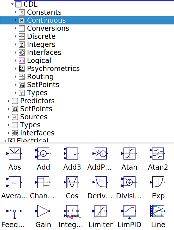
Fig. 7.2 Screenshot of CDL library.
The CDL library contains elementary blocks that are used to compose control sequences. The functionality of elementary blocks, but not their implementation, is part of the CDL specification. Thus, in the most general form, elementary blocks can be considered as functions that for given parameters \(p\), time \(t\) and internal states \(x(t)\), map inputs \(u(t)\) to new outputs \(y(t)\), e.g.,
Control providers who support CDL need to be able to implement the same functionality as is provided by the elementary CDL blocks.
[CDL implementations are allowed to use a different implementation of the elementary blocks, because the implementation is language specific. However, implementations shall have the same inputs, outputs and parameters, and they shall compute the same response for the same value of inputs and state variables.]
Users are not allowed to add new elementary blocks. Rather, users can use the existing elementary blocks to implement composite blocks (Section 7.12).
Note
The elementary blocks can be browsed in any of these ways:
Open a web browser at https://simulationresearch.lbl.gov/modelica/releases/latest/help/Buildings_Controls_OBC_CDL.html.
Download https://github.com/lbl-srg/modelica-buildings/archive/master.zip, unzip the file, and open
Buildings/package.moin the graphical model editor of OpenModelica, Impact, or Dymola. All models in the Examples and Validation packages can be simulated with these tools.
An actual implementation of an elementary block looks as follows, where we omitted the annotations that are used for graphical rendering:
block AddParameter "Output the sum of an input plus a parameter"

  parameter Real p "Value to be added";

  Interfaces.RealInput u "Connector of Real input signal";
  Interfaces.RealOutput y "Connector of Real output signal";

equation
  y = u + p;

  annotation(Documentation(info("
  <html>
  <p>
  Block that outputs <code>y = u + p</code>,
  where <code>p</code> is parameter and <code>u</code> is an input.
  </p>
  </html>"));

end AddParameter;
For the complete implementation, see the github repository.
7.7. Instantiation
7.7.1. Parameter Declaration and Assigning of Values to Parameters
Parameters are values that do not depend on time. The values of parameters can be changed during run-time through a user interaction with the control program (such as to change a control gain), unless a parameter is a structural parameter.
The declaration of parameters and their values is identical to Modelica,
but we limit the type of expressions that are allowed in such assignments. In particular,
for Boolean parameters, we allow expressions involving
and, or and not and the function fill(..) in Table 7.2.
For Real and Integer, expressions are allowed that involve
the basic arithmetic functions
+,-,*,-,the relations
>,>=,<,<=,==,<>,calls to the functions listed in Table 7.2.
[For example, to instantiate a block that multiplies its input by a parameter, one would write
CDL.Reals.MultiplyByParameter gai(k=-1) "Constant gain of -1" annotation(...);
where the documentation string is optional. The annotation is typically used for the graphical positioning of the instance in a block diagram.]
7.7.2. Functions
CDL provide built-in functions that can be used when assigning values of parameters and attributes of constants, parameters, inputs, and outputs. Table 7.2 lists the supported functions.
Function |
Description |
|---|---|
|
Absolute value of |
|
Returns |
|
Returns the square root of |
|
Returns the algebraic quotient |
|
Returns the integer modulus of [Examples are |
|
Returns the integer remainder of [Examples are |
|
Returns the smallest integer not less than |
|
Returns the largest integer not greater than |
|
Returns the largest integer not greater than |
|
Returns the least element of array expression |
|
Returns the least element of the scalars |
|
Returns the greatest element of array expression |
|
Returns the greatest element of the scalars |
|
The expression The type of |
|
Returns an array that concatenates arrays
|
|
Returns the \(n_1 \times n_2 \times n_3 \times \dots\) array with all
elements equal to scalar or array
expression Recursive definition:
The function needs two or more arguments; that is |
|
Returns dimensions of an array. For \(1 \le i \le n\),
where \(n\) is the number of dimensions in |
[For example, if a controller has a parameter for the set point for the outdoor air flow rate of ten (equally sized) zones that needs to be set to \(0.1 \, \mathrm{m^3/s}\), a declaration may look like:
parameter Real VSet_flow[10](
 final unit=fill("m3/s", 10)) = fill(0.1, 10);
]
7.7.3. Evaluation of Assignment of Values to Parameters
Using expressions in parameter assignments, and propagating values of parameters
in a hierarchical formulation of a control sequence, are convenient language constructs
to express relations between
parameters. However, most of today’s building control product lines do not support
propagation of parameter values and evaluation of expressions in parameter assignments.
For CDL to be compatible with this limitation, the modelica-json translator
has optional flags, described below, that trigger the evaluation of propagated parameters,
and that evaluate expressions that involve parameters.
CDL also has a keyword called final that prevents a declaration from being changed by the user.
This can be used in a hierarchical controller to ensure that parameter values are propagated to lower level controller
in such a way that users can only change their value at the top-level location.
It can also be used in CDL to enforce that different instances of blocks have the same parameter value.
For example, if a controller samples two signals, then final could be used to ensure that they
sample at the same rate.
However, most of today’s building control product lines do not support such a language construct.
Therefore, while the CDL translator preserves the final keyword in the CDL-JSON format,
a translator from CDL-JSON to a control product line is allowed to ignore this declaration.
Note
People who implement control sequences that require that values of parameters are identical
among multiple instances of blocks
must use blocks that take these values as an input, rather than rely on the final keyword.
This could be done as explained in
these two examples:
Example 1: If a controller has two samplers called sam1 and sam2 and their parameter
samplePeriod must satisfy sam1.samplePeriod = sam2.samplePeriod for the logic to work correctly,
then the controller can be implemented using
CDL.Logical.Sources.SampleTrigger
and connect its output to two instances of
CDL.Discrete.TriggeredSampler
that sample the corresponding signals.
Example 2: If a controller normalized two input signals by dividing it by a gain k1, then
rather than using two instances of
CDL.Reals.MultiplyByParameter
with parameter k = 1/k1, one could use
a constant source
CDL.Reals.Sources.Constant
with parameter k=k1 and
two instances of
CDL.Reals.Divide,
and then connect
the output of the constant source with the inputs of the division blocks.
We will now describe how assignments of values to parameters can optionally be evaluated by the CDL translator. While such an evaluation is not preferred, it is allowed in CDL to accommodate the situation that most building control product lines, in contrast to modeling tools such as Modelica, Simulink or LabVIEW, do not support the propagation of parameters, nor do they support the use of expressions in parameter assignments.
Consider the statement
parameter Real pRel(unit="Pa") = 50 "Pressure difference across damper";

CDL.Reals.Sources.Constant con(
  k = pRel) "Block producing constant output";
CDL.Logical.Hysteresis hys(
  uLow  = pRel-25,
  uHigh = pRel+25) "Hysteresis for fan control";
Some building control product lines will need to evaluate this at translation because they cannot propagate parameters and/or cannot evaluate expressions.
To lower the barrier for the development of a CDL translator to a control product line,
the modelica-json translator has two flags.
One flag, called evaluatePropagatedParameters will cause the translator to evaluate the propagated parameter,
leading to a CDL-JSON declaration that is equivalent to the declaration
CDL.Reals.Sources.Constant con(
  k(unit="Pa") = 50) "Block producing constant output";
CDL.Logical.Hysteresis hys(
  uLow  = 50-25,
  uHigh = 50+25) "Hysteresis for fan control";
- Note
the
parameter Real pRel(unit="Pa") = 50has been removed as it is no longer used anywhere.the parameter
con.khas now theunitattribute set as this information would otherwise be lost.the parameter
hys.uLowhas the unit not set because the assignment involves an expression. As expressions can be used to convert a value to a different unit, the unit will not be propagated if the assignment involves an expression.
Another flag called evaluateExpressions will cause all mathematical expressions to be evaluated,
leading to a CDL-JSON declaration that is equivalent to the CDL declaration
parameter Real pRel(unit="Pa") = 50 "Pressure difference across damper";

CDL.Reals.Sources.Constant con(
  k = pRel) "Block producing constant output";
CDL.Logical.Hysteresis hys(
  uLow  = 25,
  uHigh = 75) "Hysteresis for fan control";
If both evaluatePropagatedParameters and evaluateExpressions are set, the result would be
equivalent of the declaration
CDL.Reals.Sources.Constant con(
  k(unit="Pa") = 50) "Block producing constant output";
CDL.Logical.Hysteresis hys(
  uLow  = 25,
  uHigh = 75) "Hysteresis for fan control";
Clearly, use of these flags is not preferred, but they have been introduced to accomodate the capabilities that are present in most of today’s building control product lines.
Note
A commonly used construct in control sequences is to declare a parameter and
then use the parameter once to assign the value of a block in this sequences.
In CDL, this construct looks like
parameter Real pRel(unit="Pa") = 50 "Pressure difference across damper";
CDL.Reals.Sources.Constant con(k = pRel) "Block producing constant output";
Note that the English language sequence description would typically refer to the parameter pRel.
If this is evaluated during translation due to the evaluatePropagatedParameters flag,
then pRel would be removed as it is no longer used.
Hence, such a translation should then rename the block con to pRel, e.g., it should
produce a sequence that is equivalent to the CDL declaration
CDL.Reals.Sources.Constant pRel(k = 50) "Block producing constant output";
In this way, references in the English language sequence to pRel are still valid.
7.7.4. Conditionally Removing Instances
Instances of blocks, inputs, and outputs can be conditionally removed by using an if clause.
Removing these instances also removes their connections between inputs and outputs.
This allows, for example, to have an implementation of a controller that optionally takes as an input the number of occupants in a zone.
An example code snippet is
parameter Boolean have_occSen=false
  "Set to true if zones have occupancy sensor";

CDL.Interfaces.IntegerInput nOcc if have_occSen
  "Number of occupants"
    annotation (__cdl(default = 0));

CDL.Reals.MultiplyByParameter gai(
  k = VOutPerPer_flow) if have_occSen
    "Outdoor air per person";
equation
connect(nOcc, gai.u);
By the Modelica language definition, all connections (Section 7.10)
to nOcc will be removed if have_occSen = false.
Some building automation systems do not allow to conditionally removing instances
of blocks, inputs and outputs, and their connections. Rather, these instances
are always present, and a value for the input must be present.
To accomodate this case, every input connector that can be conditionally removed
can declare a default value of the form __cdl(default = value),
where value is the default value that will be used
if the building automation system does not support conditionally removing instances.
The type of value must be the same as the type of the connector.
For Boolean connectors, the allowed values are true and false.
If the __cdl(default = value) annotation is absent, then the following values are
assumed as default:
For RealInput, the default values are:
If
unit=K: Ifquantity="TemperatureDifference", the default is \(0\) K, otherwise it is \(293.15\) K.If
unit=Pa: Ifquantity="PressureDifference", the default is \(0\) Pa, otherwise it is \(101325\) Pa.For all other units, the default value is \(0\).
For
IntegerInput, the default value is \(0\).For
BooleanInput, the default value isfalse.
Note that output connectors must not have a specification of a default value, because if a building automation system cannot conditionally remove instances, then the block (or input connector) upstream of the output will always be present (or will have a default value).
7.7.5. Point list
From CDL-conforming sequences, point lists can be generated.
[This could be accomplished using the modelica-json tool,
see Fig. 7.1.]
For point lists,
the connectors
RealInputandIntegerInputare analog inputs.the connectors
RealOutputandIntegerOutputare analog outputs.the connectors
BooleanInputandBooleanOutputare digital inputs and outputs.
7.7.5.1. Annotations that Cause Point Lists to be Generated
The vendor annotation __cdl(generatePointlist=Boolean, controlledDevice=String) at the class level specifies
that a point list of the sequence is generated.
If not specified, it is assumed that __cdl(generatePointlist=false).
The key controlledDevice is optional. It can be used to list the device that is being controlled.
Its value will be written to the point list, but not used otherwise, see Table 7.3 for an example.
When instantiating a block, the __cdl(generatePointlist=Boolean) annotation
can also be added to the instantiation clause,
and it will override the class level declaration.
[For example,
block A
  MyController con1;
  MyController con2 annotation(__cdl(generatePointlist=false));
  annotation(__cdl(generatePointlist=true));
end A;
generates a point list for A.con1 only, while
block A
  MyController con1;
  MyController con2 annotation(__cdl(generatePointlist=true));
  annotation(__cdl(generatePointlist=false));
end A;
generates a point list for A.con2 only.]
The generatePointlist annotation can be propagated down in a composite block (see Section 7.12)
by specifying in the instantiation clause the annotation
__cdl(propagate(instance="subCon1", generatePointlist=true))
Controllers deeper in the hierarchy are referred to using the dot notation, such as in
instance="subCon1.subSubCon1" where subSubCon1 is an instance of an elementary or composite block in subCon1.
The value of instance= must be an elementary block (see Section 7.6)
or a composite block (see Section 7.12). It
must declared, but it can be conditionally removed (see Section 7.7.4),
in which case the declaration can safely be ignored.
Higher-level declarations override lower-level declarations.
[For example, assume con1 has a block called subCon1. Then, the declaration
MyController con1 annotation(__cdl(propagate(instance="subCon1", generatePointlist=true)));
sets generatePointlist=true in the instance con1.subCon1.]
There can be any number of propagate(...) annotations for a controller.
[Specifying multiple propagate(...) annotations is useful for composite controllers.
For example,
MyController con1 annotation(
  __cdl(
    propagate(instance="subCon1",            generatePointlist=true),
    propagate(instance="subCon1.subSubCon1", generatePointlist=true),
    propagate(instance="subCon1.subSubCon2", generatePointlist=false)
  )
);
allows a fine grained propagation to individual blocks of a composite block. ]
7.7.5.2. Annotations for Connectors
Connectors (see Section 7.8) can have a vendor annotation of the form
__cdl(connection(hardwired=Boolean))
The field hardwired specifies whether the connection should be hardwired or not,
the default value is false.
Connectors can also have a vendor annotation of the form
__cdl(trend(interval=Real, enable=Boolean))
The field interval must be specified and its value is the trending interval in seconds.
Set interval = 0 to trend the value each time it changes.
The field enable is optional, with default value of true, and
it can be used to overwrite the value used in the sequence declaration.
Similar to generatePointlist, the connection and trend annotations can be
propagated. If a composite block contains a block con1, which in turn contains a block subCon1 that
has an input u, the declaration
MyController con1 annotation(
  __cdl(propagate(instance="subCon1.u", connection(hardwired=Boolean)));
can be used to set the type of connection of input (or output) con1.subCon1.u.
The value assigned to instance must be the instance name of a connector.
Similarly, the declaration
MyController con1 annotation(
  __cdl(propagate(instance="subCon1.u", trend(interval=Real, enable=Boolean)));
can be used to set how to trend that input (or output).
These statements can also be combined into
MyController con1 annotation(
  __cdl(propagate(instance="subCon1.u", connection(hardwired=Boolean),
                                        trend(interval=Real, enable=Boolean)));
As in Section 7.7.5.1,
the value assigned to
instancemust be the name of an instance that exist, (but it can be conditionally removed in which case the annotation can be ignored),higher-level declarations override lower-level declarations, and
any number of
propagate(...)annotations can be present.
[For example, consider the pseudo-code
block Controller

   Interfaces.RealInput u1
     annotation(__cdl(connection(hardwired=true), trend(interval=60, enable=true)));
   Interfaces.RealInput u2
     annotation(__cdl(connection(hardwired=false),
                      trend(interval=120, enable=true),
                      propagate(instance="con1.u1",
                        connection(hardwired=false),
                        trend(interval=120, enable=true))));

   MyController con1 annotation(__cdl(generatePointlist=true));
   MyController con2 annotation(__cdl(generatePointlist=false,
                                      propagate(instance="subCon1", generatePointlist=true),
                                      propagate(instance="subCon2", generatePointlist=true)));

equation
   connect(u1, con1.u1);
   connect(u2, con1.u2);
   connect(u1, con2.u1);
   connect(u2, con2.u2);

   annotation(__cdl(generatePointlist=true));
end Controller;

...

block MyController
   Interfaces.RealInput u1
     annotation(__cdl(connection(hardwired=false), trend(interval=120, enable=true)));
   Interfaces.RealInput u2
     annotation(__cdl(connection(hardwired=true),  trend(interval=60,  enable=true)));
   ...
   SubController1 subCon1;
   SubController2 subCon2;
   ...
   annotation(__cdl(generatePointlist=true));
end MyController;
The translator will generate an annotation propagation list as shown below. There will be point
list for Controller, Controller.con1, Controller.con2.subCon1 and
Controller.con2.subCon1. Also, the annotation connection(hardwired=true), trend(interval=60, enable=true)
of con1.u2 will be overridden as connection(hardwired=false), trend(interval=120, enable=true).
[
  {
    "className": "Controller",
    "points": [
      {
        "name": "u1",
        "hardwired": true,
        "trend": {
          "enable": true,
          "interval": 60
        }
      },
      {
        "name": "u2",
        "hardwired": false,
        "trend": {
          "enable": true,
          "interval": 120
        }
      }
    ]
  },
  {
    "className": "Controller.con1",
    "points": [
      {
        "name": "u1",
        "hardwired": false,
        "trend": {
          "enable": true,
          "interval": 120
        }
      },
      {
        "name": "u2",
        "hardwired": false,
        "trend": {
          "enable": true,
          "interval": 120
        }
      }
    ]
  },
  {
    "className": "Controller.con2.subCon1",
    "points": [
      ...
    ]
  },
  {
    "className": "Controller.con2.subCon2",
    "points": [
      ...
    ]
  }
]
]
[For an example of a point list generation, consider the pseudo-code shown below.
within Buildings.Controls.OBC.ASHRAE.G36G36.TerminalUnits.Reheat
block Controller "Controller for room VAV box with reheat"
   ...;
   CDL.Interfaces.BooleanInput uWin "Windows status"
      annotation (__cdl(connection(hardwired=true),
                        trend(interval=60, enable=true)));
   CDL.Interfaces.RealOutput yVal "Signal for heating coil valve"
      annotation (__cdl(connection(hardwired=false),
                        trend(interval=60, enable=true)));
   ...
annotation (__cdl(generatePointlist=true, controlledDevice="Terminal unit"));
It specifies that a point list should be generated for the sequence that controls the
system or equipment specified by controlledDevice, that uWin is a
digital input point that is hardwired, and that yVal is an analog output point that
is not hardwired. Both of them can be trended with a time interval of 1 minute.
The point list table will look as shown in Table 7.3.
System/Equipment |
Name |
Type |
Hardwired? |
Trend [s] |
Description |
|---|---|---|---|---|---|
Terminal unit |
|
DI |
Yes |
60 |
Windows status |
Terminal unit |
|
AO |
No |
60 |
Signal for heating coil valve |
… |
… |
… |
… |
… |
… |
]
7.8. Connectors
Blocks expose their inputs and outputs through input and output connectors.
The permissible connectors are implemented in the package
CDL.Interfaces, and are
BooleanInput, BooleanOutput,
IntegerInput, IntegerOutput,
RealInput and RealOutput.
Connectors must be in a public section.
Connectors can carry scalar variables, vectors or arrays of values (each having the same data type). For arrays, the connectors need to be explicitly declared as an array.
[ For example, to declare an array of nin input signals, use
parameter Integer nin(min=1) "Number of inputs";

Interfaces.RealInput u[nin] "Connector for 2 Real input signals";
]
Note
In general, today’s building control product lines only support scalar variables on graphical connections. This leads to the situation that different control sequences need to be implemented for any combination of equipment. For example, if only scalars are allowed in connections, then a chiller plant with two chillers needs a different sequence than a chiller plant with three chillers. With vectors, however, one sequence can be implemented for chiller plants with any number of chillers. This is currently done when implementing sequences from ASHRAE RP-1711 in CDL.
If control product lines do not support vectors on connections, then during translation from CDL to the control product line, the vectors (or arrays) can be flattened. For example, blocks of the form
parameter Integer n = 2 "Number of blocks";
CDL.Reals.Sources.Constant con[n](k={1, 2});
CDL.Reals.MultiSum mulSum(nin=n); // multiSum that contains an input connector u[nin]
equation
connect(con.y, mulSum.u);
could be translated to the equivalent of
CDL.Reals.Sources.Constant con_1(k=1);
CDL.Reals.Sources.Constant con_2(k=1);
CDL.Reals.MultiSum mulSum(nin=2);
equation
connect(con_1.y, mulSum.u_1);
connect(con_2.y, mulSum.u_2);
E.g., two instances of CDL.Reals.Sources.Constant are used, the vectorized input mulSum.u[2] is flattened
to two inputs, and two separate connections are instantiated.
This will preserve the control logic, but the components will need to be graphically rearranged after translation.
7.9. Equations
After the instantiations (Section 7.7),
a keyword equation must be present
to introduce the equation section.
The equation section can only contain
connections (Section 7.10) and
annotations (Section 7.11).
Unlike in Modelica, an equation section shall not contain
equations such as y=2*u; or commands such as for, if,
while and when.
Furthermore, unlike in Modelica, there shall not be an initial equation,
initial algorithm or algorithm
section. (They can however be part of a elementary block.)
7.10. Connections
Connections connect input to output connector (Section 7.8). For scalar connectors, each input connector of a block needs to be connected to exactly one output connector of a block. For vectorized connectors, or vectorized instances with scalar connectors, each (element of an) input connector needs to be connected to exactly one (element of an) output connector.
Connections are listed after the instantiation of the blocks in an equation
section. The syntax is
connect(port_a, port_b) annotation(...);
where annotation(...) is used to declare
the graphical rendering of the connection (see Section 7.11).
The order of the connections and the order of the arguments in the
connect statement does not matter.
[For example, to connect an input u of an instance gain to the output
y of an instance maxValue, one would declare
CDL.Reals.Max maxValue "Output maximum value";
CDL.Reals.MultiplyByParameter gain(k=60) "Gain";

equation
  connect(gain.u, maxValue.y);
]
Only connectors that carry the same data type (Section 7.4.1) can be connected.
Attributes of the variables that are connected are handled as follows:
If the
quantity,unit,minormaxattributes are set to a non-default value for both connector variables, then they must be equal.If only one of the two connector variables declares the
quantity,unit,minormaxattribute, then this value is applied to both connector variables.If two connectors have different values for the
displayUnitattribute, then either can be used. [It is a quality of the implementation that a warning is issued if declarations are inconsistent. However, becausedisplayUnitdoes not affect the computations in the sequence, the connection is still valid.]
[For example,
Reals.Max maxValue(y(unit="m/s")) "Output maximum value";
Reals.MultiplyByParameter gain(                     k=60) "Gain";
Reals.MultiplyByParameter gainOK(   u(unit="m/s" ), k=60) "Gain";
Reals.MultiplyByParameter gainWrong(u(unit="kg/s"), k=60) "Gain";

equation
  connect(gain.u,      maxValue.y); // This sets gain.u(unit="m/s")
                                    // as gain.u does not declare its unit
  connect(gainOK.u,    maxValue.y); // Correct, because unit attributes are consistent
  connect(gainWrong.u, maxValue.y); // Not allowed, because of inconsistent unit attributes
]
Signals shall be connected using a connect statement;
assigning the value of a signal in the instantiation of the
output connector is not allowed.
[This ensures that all control sequences are expressed as block diagrams. For example, the following model is valid
block MyAdderValid
  Interfaces.RealInput u1;
  RealInput u2;
  Interfaces.RealOutput y;
  Reals.Add add;
equation
  connect(add.u1, u1);
  connect(add.u2, u2);
  connect(add.y,  y);
end MyAdderValid;
whereas the following implementation is not valid in CDL, although it is valid in Modelica
block MyAdderInvalid
  Interfaces.RealInput u1;
  Interfaces.RealInput u2;
  Interfaces.RealOutput y = u1 + u2; // not allowed
end MyAdderInvalid;
]
7.11. Annotations
Annotations follow the same rules as described in the following Modelica 3.6 Specifications
18.2 Annotations for Documentation
18.6 Annotations for Graphical Objects, with the exception of
18.6.7 User input
18.8 Annotations for Version Handling
[For CDL, annotations are primarily used to graphically visualize block layouts, graphically visualize input and output signal connections, and to declare vendor annotations, (Sec. 18.1 in Modelica 3.6 Specification), such as to specify default value of connector as below.]
CDL also uses annotations to declare default values for conditionally removable input connectors, see Section 7.7.4.
For CDL implementations of sources such as ASHRAE Guideline 36, any instance,
such as a parameter, input or output, that is not provided in
the original documentation shall be annotated. For instances,
the annotation is __cdl(InstanceInReference=false) while for parameter values,
the annotation is __cdl(ValueInReference=false). For both, if not specified
the default value is true.
[ A specification may look like
parameter Real anyOutOfScoMult(
  final unit = "1",
  final min = 0,
  final max = 1)=0.8
  "Outside of G36 recommended staging order chiller type SPLR multiplier"
  annotation(Evaluate=true, __cdl(ValueInReference=false));
]
Note
This annotation is not provided for parameters that are in general not specified in the ASHRAE Guideline 36, such as hysteresis deadband, default gains for a controller, or any reformulations of ASHRAE parameters that are needed for sequence generalization, for instance a matrix variable used to indicate which chillers are used in each stage.
7.12. Composite Blocks
A composite block is a block that is composed of any number of instances of
constants,
parameters,
input connectors,
output connectors,
elementary blocks, and
other composite blocks.
Composite blocks also contain an equation section
in which connections are instantiated to connect inputs connectors and output connectors
of the composite block and its elementary and composite blocks.
These rules allow the definition of composite blocks in a library,
and the instantiation and possible configuration of these instances
to implement a particular control sequence.
A simple example of a composite block that multiplies one of its inputs, adds it to the other input and produces at its output connector the sum is shown in Fig. 7.3.

Fig. 7.3 Example of a composite control block that outputs \(y = \min( k \, e, \, y_{max})\) where \(k\) is a parameter.
Each composite block shall be stored on the file system under the name of the composite block
with the file extension .mo, and with each package name being a directory.
The name shall be an allowed Modelica class name.
[For example, if a user specifies a new composite block MyController.MyAdder, then it
shall be stored in the file MyController/MyAdder.mo on Linux or OS X, or MyController\MyAdder.mo
on Windows.]
[The following statement, when saved as CustomPWithLimiter.mo, is the
declaration of the composite block shown in Fig. 7.3
block CustomPWithLimiter
  "Custom implementation of a P controller with variable output limiter"

  parameter Real k "Constant gain";

  CDL.Interfaces.RealInput yMax "Maximum value of output signal"
    annotation (Placement(transformation(extent={{-140,20},{-100,60}})));

  CDL.Interfaces.RealInput e "Control error"
    annotation (Placement(transformation(extent={{-140,-60},{-100,-20}})));

  CDL.Interfaces.RealOutput y "Control signal"
    annotation (Placement(transformation(extent={{100,-10},{120,10}})));

  CDL.Reals.MultiplyByParameter gain(final k=k) "Constant gain"
    annotation (Placement(transformation(extent={{-60,-50},{-40,-30}})));

  CDL.Reals.Min minValue "Outputs the minimum of its inputs"
    annotation (Placement(transformation(extent={{20,-10},{40,10}})));
equation
  connect(yMax, minValue.u1) annotation (
    Line(points={{-120,40},{-120,40},{-20,40},{-20, 6},{18,6}},
         color={0,0,127}));
  connect(e, gain.u) annotation (
    Line(points={{-120,-40},{-92,-40},{-62,-40}},
         color={0,0,127}));
  connect(gain.y, minValue.u2) annotation (
    Line(points={{-39,-40},{-20,-40},{-20,-6}, {18,-6}},
         color={0,0,127}));
  connect(minValue.y, y) annotation (
     Line(points={{41,0},{110,0}},
          color={0,0,127}));

  annotation (Documentation(info="<html>
<p>
Block that outputs <code>y = min(yMax, k*e)</code>,
where
<code>yMax</code> and <code>e</code> are real-valued input signals and
<code>k</code> is a parameter.
</p>
</html>"));
end CustomPWithLimiter;
Composite blocks are needed to preserve grouping of control blocks and their connections, and are needed for hierarchical composition of control sequences.]
7.13. Extension Blocks
To support functionalities that cannot, or may be hard to, implement with a composite block, extension blocks are introduced.
Note
Extension blocks are introduced to allow implementation of blocks that contain statistical functions such as for regression, fault detection and diagnostics methods, or state machines for operation mode switches, as well as proprietary code.
Extension blocks are also suited to propose new elementary blocks for later inclusion
in ASHRAE Standard 231P. In fact, elementary blocks are implemented using
extension blocks, except that the annotation __cdl(extensionBlock=true) (see below)
is not present because tools can recognize them because they are stored in the CDL package.
In CDL, extension blocks must have the annotations
annotation(__cdl(extensionBlock=true))
This annotation allows translators to recognize them as extension blocks.
Extension blocks are equivalent to the class block in Modelica.
Thus, extension blocks can contain any declarations that are allowed in a Modelica block.
Note
The fact that extension blocks allow any declaration
that is allow in a Modelica block
implies that extension blocks can have any number of parameters, inputs and outputs,
identical to composite blocks. It also implies that extension blocks can be used to
call code, for example in C or from a compiled library,
import a Functional Mockup Unit that may contain a process model or a fault detection and diagnostics method, and
implement state machines.
For example, the demand response client
Buildings.Controls.DemandResponse.Client
would be an extension block if it were to contain the annotation __cdl(extensionBlock=true),
as would the Kalman filter that is used in the Example
Buildings.Utilities.IO.Python_3_8.Examples.KalmanFilter.
Translation of an extension block to json must reproduce the following:
All public parameters, inputs and outputs.
A Functional Mockup Unit for Model Exchange or for Co-simulation, version 2.0, with the file name being the full class name and the extension being
.fmu.
Note
With OpenModelica 1.20.0, a Functional Mockup Unit for Model Exchange 2.0 of an extension block can be generated with the commands:
echo "loadFile(\"Buildings/package.mo\");" > translate.mos
echo "translateModelFMU(Buildings.Controls.OBC.CDL.Reals.PID);" >> translate.mos
omc translate.mos
This will generate the fmu Buildings.Controls.OBC.CDL.Reals.PID.fmu.
7.14. Replaceable Blocks
CDL allows the use of the Modelica replaceable, constrainedby and redeclare keywords.
The replaceable keyword allows to replace a block by another block when translating a composite block.
To declare a block as replaceable, the syntax is
replaceable ClassName instanceName comment annotation;
where ClassName is the name of the class, instanceName is the name of the instance, and
comment and annotation are optional comments or annotations.
Optionally, the constrainedby keyword can be added after instanceName to constrain what blocks can be used when
redeclaring the replaceable block. The declaration is then
replaceable ClassName instanceName constrainedby NameOfConstrainingClass parameterBindings comment annotation;
where NameOfConstrainingClass is the name of the constraining class, and
parameterBindings is optional and can be used to assign parameters,
with or without the final keyword.
[
For example, consider a composite block that has a PID controller.
Suppose the developer of the composite block
uses its custom PID controller called MyPID, and the developer
wants to allow a user of the composite block to replace the PID controller with any custom PID controller,
as long as it provides the inputs, outputs, and parameters of the elementary block of the PID controller CDL.Reals.PID.
Then, the composite block can be implemented as
block SomeCompositeBlock "A composite block in a library"
...
parameter Real k = 2 "Proportional gain";
replaceable MyPID con constrainedby CDL.Reals.PID(
 k=k)
 "PID controller";
...
end SomeCompositeBlock;
Because of the constrainedby clause,
a user of the composite block can replace the controller MyPID with any other PID controller
that also provides the inputs, outputs, and parameters that are present in CDL.Reals.PID.
Moreover, the assignment
k=k will also be applied when the controller is redeclared.
Such a redeclaration in which a block MyPreferredPID is used for the instance con
can be done using
block SomeCompositeBlock "A composite block in a library"

   parameter Real k = 2 "Proportional gain";

   replaceable Buildings.Controls.OBC.CDL.Reals.PID conPID
     constrainedby Buildings.Controls.OBC.CDL.Reals.PID(k=k)
     "PID controller"
     annotation(
    Placement(transformation(extent = {{-10, -10}, {10, 10}})));

   annotation(
    uses(Buildings(version = "12.0.0")));

end SomeCompositeBlock;
In a redeclare statement, any parameters can be assigned, for example by writing
redeclare MyPreferredPID conPID(Ti=60), which sets the parameter Ti to 60.
The constrainedby keyword can also be used to allow use of a block that has other parameters
or inputs. A simple example is
package ReplaceableExample
  block ReplaceableBlock
    replaceable Buildings.Controls.OBC.CDL.Reals.Sources.Constant con(k=1)
      constrainedby Buildings.Controls.OBC.CDL.Reals.Sources.CivilTime
     "Replaceable block, constrained by a block that imposes as a requirement
     that the redeclaration provides a block with output y (but no parameter k is needed)";
  end ReplaceableBlock;

  block MyNewBlock "Composite block, with sou replaced by a Pulse with period=0.1"
    ReplaceableBlock repBlo(
      redeclare Buildings.Controls.OBC.CDL.Reals.Sources.Pulse con(period=0.1));
  end MyNewBlock;
  annotation (
    uses(Buildings(version = "11.0.0")));
end ReplaceableExample;
In the above code, the constrainedby keyword specifies the block CivilTime.
As CivilTime has only a RealOutput called y, but no parameters or inputs,
the Constant block can be
replaced by a Pulse block, although Pulse has no parameter k.
Without the constrainedby CDL.Reals.Sources.CivilTime clause,
Pulse could not have been used as it has no parameter k.
]
When translating CDL to CXF, the keywords replaceable, constrainedby and redeclare
need to be evaluated and removed. E.g., they are not present in CXF.
7.15. Extension of a Composite Block
A composite block can have a single extends statement.
The extends statement must reference another Composite Block,
but it cannot extend an Elementary Block or an Extension Block.
The extends statement can have any number of declarations that assign
a parameter value or parameter attributes.
Note
There are three restrictions compared to the Modelica Language Specification [Mod23]:
Only a single
extendsstatement is allowed. This is for simplicity because twoextendsstatements could require having to reconcile two different hierarchy trees that ultimately extend from the same base block, but may assign different values to a parameter that is inherited from the common base block. Such a case would be for examplepackage MultipleExtends block A0 extends Buildings.Controls.OBC.CDL.Reals.Sources.Constant(k=0); end A0; block A1 extends Buildings.Controls.OBC.CDL.Reals.Sources.Constant(k=1); end A1; block NotValid "Block that is not valid" extends A0; extends A1; end NotValid; annotation( uses(Buildings(version = "12.0.0")), Documentation( info = "<p> Package with a block that is not valid CDL due to multiple extends statements. </p>")); end MultipleExtends;
Note that in Modelica, multiple
extendsare allowed, but the blockNotValidis not valid and tools will issue an error message.The
breakkeyword for component deselection is not allowed.Modelica allows to assign a value to a variable declared as an
input. This is not allowed in CDL. This restriction avoids that input connectors can no longer be graphically connected (as they then would have two bindings to a value, causing the block to be overdetermined).
[
A simple illustrative example of an extends statement would be to
extends the block OBC.Utilities.PIDWithInputGains,
restricts its output to be always between 0 and 1,
and adding an output connector that can be used to access the control error.
This could be accomplished as
block MyPID
  extends Buildings.Controls.OBC.Utilities.PIDWithInputGains(
    final yMin = 0,
    final yMax = 1);

  Buildings.Controls.OBC.CDL.Interfaces.RealOutput error
    "Control error"
    annotation(
      Placement(
        transformation(
	  origin = {240, -120},
	  extent = {{-20, -20}, {20, 20}}),
        iconTransformation(
	  origin = {120, -60},
	  extent = {{-20, -20}, {20, 20}})));
equation
  connect(controlError.y, error) annotation(
    Line(
      points = {{-178, -6}, {-160, -6},
                {-160, -120}, {240, -120}},
      color = {0, 0, 127}));
  annotation(
    uses(Buildings(version = "12.0.0")),
    Documentation(
      info = "<p>
PID controller that extends the PID controller
with input gains, and that limits the output
between 0 and 1, and
adds an output connector that reports
the control error.
</p>"));

end MyPID;
]
The extends statement can also have any number of redeclare statements (Section 7.14).
[For example, in the block below, the controller with name conPID is replaced
with the block OBC.CDL.Reals.PIDWithReset.
model MyBlockWithRedeclare
  extends SomeCompositeBlock(
    redeclare Buildings.Controls.OBC.CDL.Reals.PIDWithReset conPID);

end MyBlockWithRedeclare;
]
In a replaceable declaration, the optional constraining-clause defines a constraining type. Any modifications following the constraining type name are applied both for the purpose of defining the actual constraining type, and they are automatically applied in the declaration and in any subsequent redeclaration. The precedence order is that declaration modifiers override constraining type modifiers.
If the constraining-clause is not present in the original declaration (i.e., the non-redeclared declaration), then the following applies:
The type of the declaration is also used as a constraining type.
The modifiers for subsequent redeclarations and constraining type are the modifiers on the component or short-class-definition if that is used in the original declaration, otherwise empty.
[ Consider the following example, and see also Section 7.3.2 in [Mod23]:
model Constraints
  record BaseRecord
    parameter Integer param=0;
  end BaseRecord;

  record Record
    extends BaseRecord(final param=1);
  end Record;

  model Model
    parameter Integer param=2;
    // OpenModelica errors because param is declared final
    replaceable parameter BaseRecord rec constrainedby BaseRecord(param=param);
  end Model;

  // Overriding by param=param from the constraining clause:
  // OpenModelica and Dymola errors,
  // Modelon OPTIMICA evaluates to 2.
  Model component1(redeclare Record rec);

   // Precedence of declaration over constraining clause from
   // https://specification.modelica.org/maint/3.5/inheritance-modification-and-redeclaration.html#constraining-type:
   // Dymola and Modelon OPTIMICA return 1.
  Model component2(rec(final param=1));

  // Precedence of declaration over constraining clause: Dymola and OCT return 1.
  Model component3(rec=Record());
end Constraints;
]
7.16. Model of Computation
CDL uses the synchronous data flow principle and the single assignment rule, which are defined below. [The definition is adopted from and consistent with the Modelica Language Specification [Mod23].]
All variables keep their actual values until these values are explicitly changed. Variable values can be accessed at any time instant.
Computation and communication at an event instant does not take time. [If computation or communication time has to be simulated, this property has to be explicitly modeled.]
Every input connector shall be connected to exactly one output connector.
In addition, the dependency graph from inputs to outputs that directly depend on inputs shall be directed and acyclic. I.e., connections that form an algebraic loop are not allowed. [To break an algebraic loop, one could place a delay block or an integrator in the loop, because the outputs of a delay or integrator does not depend directly on the input.]
7.17. Metadata
CDL has sufficient information for tools that process CDL to generate for example point lists that list all analog temperature sensors, or to verify that a pressure control signal is not connected to a temperature input of a controller. Some, but not all, of this information can be inferred from the CDL language described above. We will use metadata, implemented through Modelica vendor annotations, to provide this additional information. In Section 7.17.1, we will explain the properties that can be inferred, and in Section 7.17.2, we will explain how to use semantic models in CDL.
Note
None of this information affects the computation of a control signal. Rather, it can be used for example to facilitate the implementation of cost estimation tools, or to detect incorrect connections between outputs and inputs.
7.17.1. Inferred Properties
To avoid that signals with physically incompatible quantities
are connected, tools that parse CDL can infer the physical quantities
from the unit and quantity attributes.
[For example, a differential pressure input signal with name u
can be declared as
Interfaces.RealInput u(
  quantity="PressureDifference",
  unit="Pa") "Differential pressure signal" annotation (...);
Hence, tools can verify that the PressureDifference is not connected
to AbsolutePressure, and they can infer that the input has units of Pascal.
Therefore, tools that process CDL can infer the following information:
Numerical value: Binary value (which in CDL is represented by a
Booleandata type), analog value, (which in CDL is represented by aRealdata type) mode (which in CDL is presented by anIntegerdata type or an enumeration, which allow for example encoding of the ASHRAE Guideline 36 Freeze Protection which has 4 stages).Source: Hardware point or software point.
Quantity: such as Temperature, Pressure, Humidity or Speed.
Unit: Unit and preferred display unit. (The display unit can be overwritten by a tool. This allows for example a control vendor to use the same sequences in North America displaying IP units, and in the rest of the world displaying SI units.)
]
7.17.2. Semantic Information
The buildings industry has started to integrate different metadata languages such as Brick and Project Haystack into their control software and technology. ASHRAE Standard 223p is another upcoming metadata language that will describe the equipment topology in buildings and also the flow of different media. This section specifies the syntax to support these metadata languages and include the semantic information represented using these languages in a CDL class.
Semantic information shall be included within the annotation keyword, using the __Buildings or
__cdl vendor annotation. __cdl shall be used when the semantic information is part of a control
sequence and __Buildings shall be used for every other instance such as equipment or a zone.
The following instances shall optionally have annotations containing semantic information:
input and output connectors (Section 7.8),
parameters (Section 7.4.2),
constants (Section 7.4.3),
connections (Section 7.10),
elementary blocks (Section 7.6),
composite blocks (Section 7.12),
extension blocks (Section 7.13), and
packages.
All semantic information shall be included under the semantic section within the __Buildings or
__cdl annotations, using the syntax shown here:
annotation (__cdl(      semantic(<semantic information>)));
annotation (__Buildings(semantic(<semantic information>)));
where <semantic information> is a place holder for the semantic information.
The semantic annotation declared in the class definition shall
optionally contain the metadataLanguageDefinition or the
naturalLanguageDefinition for each of the languages used.
The metadataLanguageDefinition and naturalLanguageDefinition
are used to provide additional information about the different metadata
languages and natural languages that are used throughout the class. The
language definitions contain information such as a short description
of the language or the URL to the webpage of the language.
The optional metadataLanguageDefinition shall have the following syntax:
annotation (__cdl(semantic(
  metadataLanguageDefinition="<metadataLanguageName> <version> <format>" ["informative text"])));
annotation (__Buildings(semantic(
  metadataLanguageDefinition="<metadataLanguageName> <version> <format>" ["informative text"])));
where <metadataLanguageName> shall be replaced with the name of the metadata language,
<version> is the mandatory entry for the version,
<format> is the mandatory field for format of the language, such as text/turtle, and
["informative text"] is an optional description of the language, such as
the URL to the language.
The version represents the version of the
<metadataLanguageName> used in a particular class. The format represents the
format that the semantic information is expressed in. The format shall be expressed using
MIME types.
The optional naturalLanguageDefinition shall have the following syntax:
annotation (__cdl(semantic(
  naturalLanguageDefinition="<naturalLanguageName>" ["informative text"])));
annotation (__Buildings(
  semantic(naturalLanguageDefinition="<naturalLanguageName>" ["informative text"])));
where <naturalLanguageName> shall be replaced with the indicator of the natural language,
represented using the ISO-639 language
codes and
["informative text"] is an optional description of the language. All
<naturalLanguageName> metadata will be in the format text/plain.
[Examples of the <metadataLanguageName> include web ontology languages (OWL) such as
Brick or ASHRAE S223p, and examples of <naturalLanguageName>
include en or es. Below is an example of how to define multiple
metadataLanguageDefinition and
naturalLanguageDefinition in a class definition annotation.
Example:
annotation (__cdl(semantic(
  metadataLanguageDefinition="Brick 1.3 text/turtle" "https://brickschema.org/ontology/1.3",
  metadataLanguageDefinition="Project-Haystack 3.9.12 application/ld+json" "https://project-haystack.org/",
  naturalLanguageDefinition="en" "Text in English language"
)));
]
The semantic
information shall be included as a metadataLanguage/metadata or a
naturalLanguage/metadata pair within the semantic section in the
__cdl or __Buildings annotation using the following syntax:
annotation (__cdl(semantic(metadataLanguage="<metadataLanguageName> <version> <format>" "<metadata>")));
annotation (__Buildings(semantic(metadataLanguage="<metadataLanguageName> <version> <format>" "<metadata>")));

annotation (__cdl(semantic(naturalLanguage="<naturalLanguageName>" "<metadata>")));
annotation (__Buildings(semantic(naturalLanguage="<naturalLanguageName>" "<metadata>")));
where <metadataLanguageName> shall be replaced with the name of the metadata
language,
<version> is an entry for the version of the metadataLanguage,
<format> is the format of the metadataLanguage, such as text/turtle,
<naturalLanguageName> shall be replaced with the ISO-639 indicator of the natural
language and
<metadata> is the metadata for that instance as specified in
<metadataLanguageName> or <naturalLanguageName> language.
Note
Depending on the metadataLanguage ("<metadataLanguageName> <version> <format>"),
the metadata can be represented in multiple formats. For example, text/turtle
and application/ld+json are a couple of formats to represent the metadata of web
ontology languages such as Brick and ASHRAE S223p. Project-Haystack metadata
can also be represented in multiple formats such as text/zinc,
text/turtle and application/ld+json.
Semantic information in the class definition annotations shall optionally be used to define class level information about the metadata languages. These include, but are not restricted to, namespace definitions (namespaces in ontologies provide a means to unambiguously interpret identifiers and make the rest of the ontology presentation more readable) and prefixes (prefixes are shortcut abbreviations and help make the semantic information more readable).
[In the example below, for the metadataLanguage "Brick 1.3 text/turtle", the class
definition annotation has been used to define the namespace prefixes and for
"Project-Haystack 3.9.12 application/ld+json", it has been used to define namespaces,
prefixes and contexts.
Example:
annotation (__cdl(semantic(
  metadataLanguage="Brick 1.3 text/turtle" "@prefix Brick: <https://brickschema.org/schema/Brick#> .
                                            @prefix bldg: <urn:bldg/> . ",
  metadataLanguage="Project-Haystack 3.9.12 application/ld+json"
                                           "{\"@context\": { \"ph\": \"https://project-haystack.org/def/ph/3.9.12#\",
                                           \"phScience\": \"https://project-haystack.org/def/phScience/3.9.12#\",
                                           \"phIoT\": \"https://project-haystack.org/def/phIoT/3.9.12#\",
                                           \"rdf\": \"http://www.w3.org/1999/02/22-rdf-syntax-ns#\",
                                           \"rdfs\": \"http://www.w3.org/2000/01/rdf-schema#\"}}")));
]
If an instance declaration contains semantic information, it overrides the semantic information of its class definition. If an instance declaration does not contain semantic information, it inherits the semantic information of its class definition.
Additionally, if there already exists a semantic model for a particular class or for an instance, it shall be referred to in the annotation using the syntax defined below:
annotation (__cdl(semantic(metadataLanguage="<metadataLanguageName> <version> <format>" "url=<path>")));
annotation (__Buildings(semantic(metadataLanguage="<metadataLanguageName> <version> <format>" "url=<path>")));

annotation (__cdl(semantic(naturalLanguage="<naturalLanguageName>" "url=<path>")));
annotation (__Buildings(semantic(naturalLanguage="<naturalLanguageName>" "url=<path>")));
where <path> shall be either a URL for a model that is on the
network or a model that is present on the file system. If the url= is
included in the metadata, the semantic model will be exported from
<path>. If url= is not included in the metadata,
<path> shall be the the metadata.
If the metadata model is present on the file system as separate file, the following syntax shall be followed:
annotation (__cdl(semantic(metadataLanguage="<metadataLanguageName> <version> <format>" "url=file:///<path/to/file>")));
annotation (__Buildings(semantic(metadataLanguage="<metadataLanguageName> <version> <format>" "url=file:///<path/to/file>")));

annotation (__cdl(semantic(naturalLanguage="<naturalLanguageName>" "url=file:///<path/to/file>")));
annotation (__Buildings(semantic(naturalLanguage="<naturalLanguageName>" "url=file:///<path/to/file>")));
[Below are examples of how to refer to an existing “Brick 1.3 text/turtle” semantic model existing on the file system at “/home/user/soda_hall/soda_brick.ttl” and a “Project-Haystack 3.9.12 application/ld+json” semantic model on the network at the URL “https://project-haystack.org/example/download/alpha.jsonld”.
Example:
annotation (__cdl(
  semantic(
    metadataLanguage="Brick 1.3 text/turtle" "url=file:///home/user/soda_hall/soda_brick.ttl")));

annotation (__cdl(
  semantic(
    metadataLanguage="Project-Haystack 3.9.12 application/ld+json" "url=https://project-haystack.org/example/download/alpha.jsonld")));
]
<instanceName>: The text <instanceName> (including the <
and > characters) within the metadata of an annotation containing semantic
information shall be replaced with the fully qualified name of the instance
that contains the semantic annotation. A fully qualified name to an instance
refers to the complete hierarchical path that specifies the instance’s
location within an object structure. This qualified name shall include all
parent instances leading up to the current instance, with each level of
instantiation separated by an underscore (“_”). If an instance is nested
within multiple levels of instance definitions, the text that
replaces <instanceName> shall reflect the entire chain of instantiation.
This avoids the user having to repeat the name of the instance and
makes it less prone to errors and inconsistencies.
[An example of CDL semantic information for an instance in a class with
multiple metadataLanguage/metadata pair is shown below.
We can see that <instanceName> has been used in the
metadata and Brick metadata will be inferred as bldg:THeaCoiSup_in a Brick:Hot_Water_Supply_Temperature_Sensor .
and the Project Haystack identifier as {"@id": "THeaCoiSup_in"}.
Example:
Modelica.Blocks.Interfaces.RealInput THeaCoiSup_in
    "Heating coil water supply temperature measurement"
    annotation (Placement(transformation(extent={{-140,-180},{-100,-140}})),
                __cdl(semantic(
                metadataLanguage="Brick 1.3 text/turtle"
                  "bldg:<instanceName> a Brick:Hot_Water_Supply_Temperature_Sensor .",
                metadataLanguage=" Project-Haystack 3.9.12 application/ld+json"
                  "{
                     \"@id\": \"_:<instanceName>\",
                     \"ph:hasTag\": [
                         {\"@id\": \"phIoT:cur\"},
                         {\"@id\": \"phIoT:hot\"},
                         {\"@id\": \"phIoT:leaving\"},
                         {\"@id\": \"phIoT:point\"},
                         {\"@id\": \"phIoT:sensor\"},
                         {\"@id\": \"phScience:temp\"},
                         {\"@id\": \"phScience:water\"}
                     ],
                     \"rdfs:label\": \" Heating Hot Water Supply Temperature\"
                  }",
                metadataLanguage="en"
                  "<instanceName> is a temperature reading input that should be hardwired to heating coil temperature sensor")));
]
<parameter>: This syntax allows for a value of a parameter to be used
within an annotation containing semantic information where the parameter
shall refer to the name of a parameter instance within the
class. The text <parameter> (including the < and > characters)
shall be replaced by the value of the parameter. The class must have an
instance of a parameter with the name specified by <parameter>,
otherwise the specification is not valid.
[In the below example, if the fully qualified name of reaFloSup is
reaFloSup, the <instanceName> will be replaced by reaFloSup.
The location of the sensor, represented by the brick:hasLocation
relationship, after replacing <instanceName> will be bldg:<zon>.
<zon> refers to the value of the zon parameter within the instantiated
reaFloSup, which is east. Hence, the completely evaluated semantic
information becomes:
bldg:reaFloSup a brick:Supply_Air_Flow_Sensor;
         brick:hasLocation bldg:east .
Example:
MyCompositeBlock.MyFlowSensor reaFloSup (zon="east") "Supply Air Flow Rate"
    annotation ( __cdl(semantic(
    metadataLanguage="Brick 1.3 text/turtle"
        "bldg:<instanceName> a brick:Supply_Air_Flow_Sensor;
               brick:hasLocation bldg:<zon> .")));
]
The semantic information of an instance shall be able to refer to the semantic information of other instances declared in the class (or in inherited classes). If the instance does not exist, the semantic model is invalid.
[In the below example, the semantic information of heating coil heaCoi is
referring to the semantic information of the hot water supply temperature sensor
THeaCoiSup_in.
 Modelica.Blocks.Interfaces.RealInput THeaCoiSup_in
     "Heating coil water supply temperature measurement"
     annotation (Placement(transformation(extent={{-140,-180},{-100,-140}})),
                 __cdl(semantic(
                 metadataLanguage="Brick 1.3 text/turtle"
                   "bldg:<instanceName> a Brick:Hot_Water_Supply_Temperature_Sensor ."
                )));

Buildings.Fluid.HeatExchangers.DryCoilEffectivenessNTU heaCoi(
  show_T=true,
  dp1_nominal=3000,
  dp2_nominal=0
  ) "Heating coil"
  annotation (Placement(transformation(extent={{118,-36},{98,-56}})),
              __Buildings(semantic(
                 metadataLanguage="Brick 1.3 text/turtle"
                   "bldg:<instanceName> a Brick:Heating_Coil ;
                               brick:hasPoint bldg:THeaCoiSup_in ."
                )));
]
If a class inherits one or more classes (CDL only allows for inheriting one class), all
the semantic information in the classes is inherited.
However, if the classes being inherited and the class inheriting it contains different
metadataLanguage or naturalLanguage due to differences in
any of <metadataLanguageName> or <version> or <format> or
<naturalLanguageName> parts of the
syntax, they shall be treated as different languages.
If an inherited replaceable instance has been replaced using the redeclare
keyword, the semantic information of the instance that replaced the original instance
shall be used, and the semantic information of the replaced class shall
be ignored. If there is no semantic information in the redeclared instance annotation,
any semantic information of the constraining clause (using the constrainedby
Modelica keyword) of the original replaceable instance shall be used. Any
semantic information in the original replaceable instance
shall not be used if it has been redeclared irrespective of the presence or absence of
semantic information in the constraining clause of the redeclared instance.