10. Controls Library
10.1. Introduction
To implement control sequences that conform to the CDL specification of Section 7, we implemented a library of elementary control blocks, and a library of control sequences that are composed of these elementary blocks, using composition rules that are specified in the CDL specification. The next two sections give a brief overview of these library. To see their implementation, browse the online documentation at https://simulationresearch.lbl.gov/modelica/releases/latest/help/Buildings_Controls_OBC.html.
10.2. CDL Library
To implement control sequences in CDL, we created the CDL library. This library contains all compositional elements of the CDL language, such as connectors for input and output signals of various types (real, integer etc.), type definitions such as for the day-of-week, and the elementary blocks that are described in Section 7.6. This library consist of about 130 elementary blocks, such as a block that adds two real-valued input signals and produces its sum as the output, a block that implements a proportional-integral-derivative controller with anti-windup, and blocks that perform basic operations on boolean signals. Thus, the CDL library defines the necessary and sufficient set of models that need to be supported by control product lines to which control sequences that are expressed in CDL can be translated to, using the process described in Section 11.3.
These elementary blocks are used to compose control sequences for mechanical systems, lighting systems and active facades as described in the next section.
10.3. Library of Control Sequences
To make ready-to-use control sequences available to building designers, researchers and control providers, we implemented control sequences for secondary HVAC systems based on ASHRAE Guideline 36, for lighting systems and for active facades.
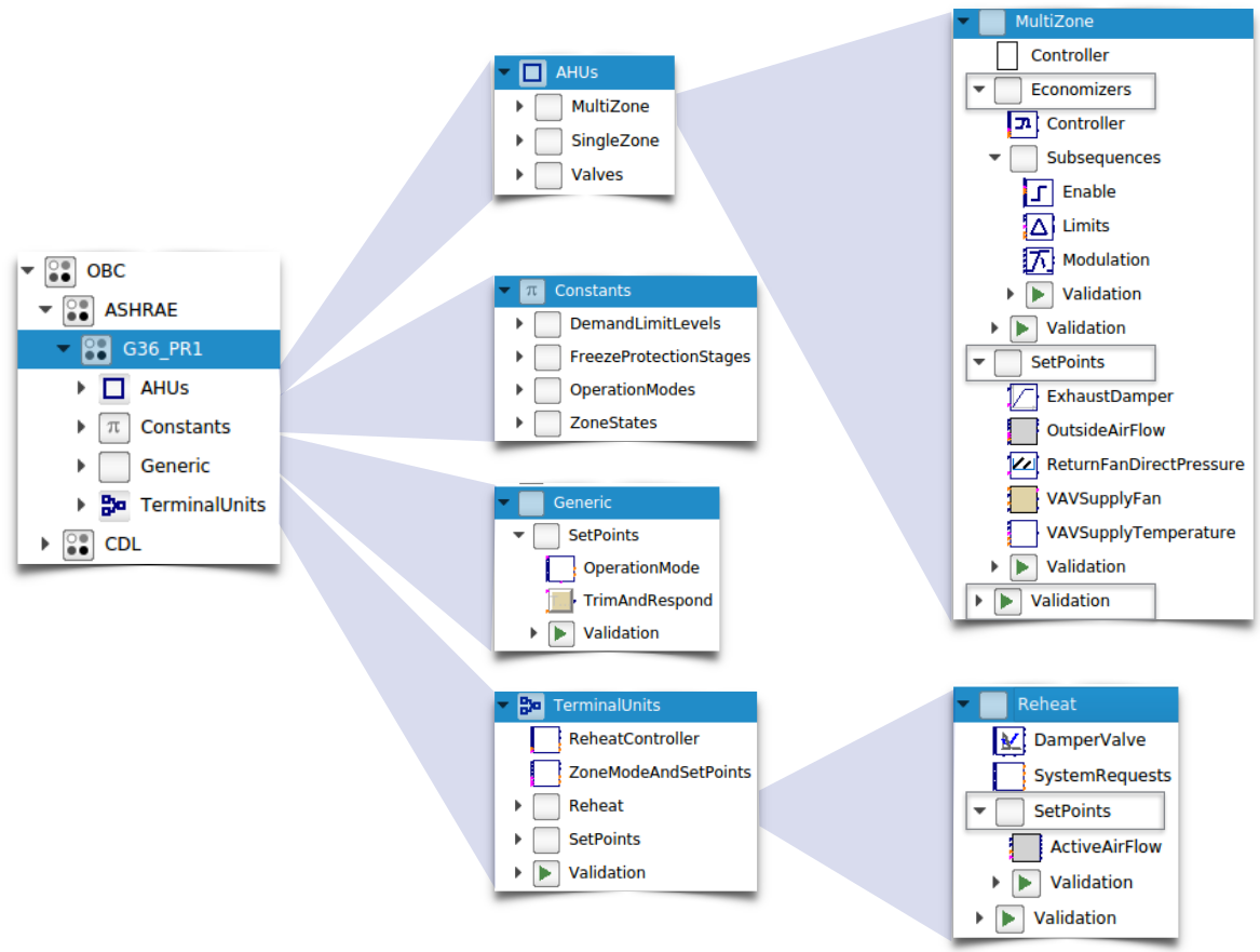
Fig. 10.1 Overview of package that includes control sequences from ASHRAE Guideline 36.
For example, Fig. 10.1 shows an overview of the control sequences that have been implemented based on ASHRAE Guideline 36. The implementation is structured hierarchically into packages for air handler units, into constants that indicate the mode of operation, into generic sequences such as for a trim and respond logic, and into sequences for terminal units. Around 30 smaller sequences are used to hierarchically compose controllers for single-zone and multi-zone VAV systems.

Fig. 10.2 Schematic view of model that uses the CDL implementation of the single zone VAV controller based on ASHRAE Guideline 36.
Every sequence contains an English language description,
an implementation using block diagram modeling, and one or more examples
that illustrate the use of the sequence. These examples
are available in the Validation package in which the sequences are used,
typically with open-loop tests.
For top-level sequences, there are also closed loop tests
available. For example Fig. 10.2
shows the schematic view of the model that evaluates the performance
of the single zone VAV controller
based on ASHRAE Guideline 36 [ZBG+20].
In this model, the controller output is connected to an HVAC system model,
which in turn is connected to a model of the building.
Sensor data from the HVAC system and the room air temperature
are fed back to the controller to form the closed loop test.
The model is available in the Modelica Buildings Library as the model
Buildings.Air.Systems.SingleZone.VAV.Examples.Guideline36.
As of Fall 2020, additional sequences are being implemented for chilled water plants and for boiler plants, following the ASHRAE Research Project Report 1711, and for optimal start-up (for heating) and cool down (for cooling).